
Heat supply optimization method for coupling absorption heat pump of thermal power plant

A technology of absorption heat pump, optimization method, applied in the direction of domestic heating, heating system, space heating and ventilation, etc.

Active Publication Date: 2020-06-09
SHANGHAI UNIVERSITY OF ELECTRIC POWER
View PDF5 Cites 2 Cited by
  • Summary
  • Abstract
  • Description
  • Claims
  • Application Information

AI Technical Summary

Problems solved by technology

[0005] The present invention is carried out to solve the above-mentioned problem of how to optimize the economic efficiency of thermal power plants and absorption heat pumps after coupling under different operating parameters, and the purpose is to provide a heat supply optimization method for thermal power plants coupled with absorption heat pumps

Method used


Image

  • Heat supply optimization method for coupling absorption heat pump of thermal power plant
  • Heat supply optimization method for coupling absorption heat pump of thermal power plant
  • Heat supply optimization method for coupling absorption heat pump of thermal power plant

Examples


Embodiment 1

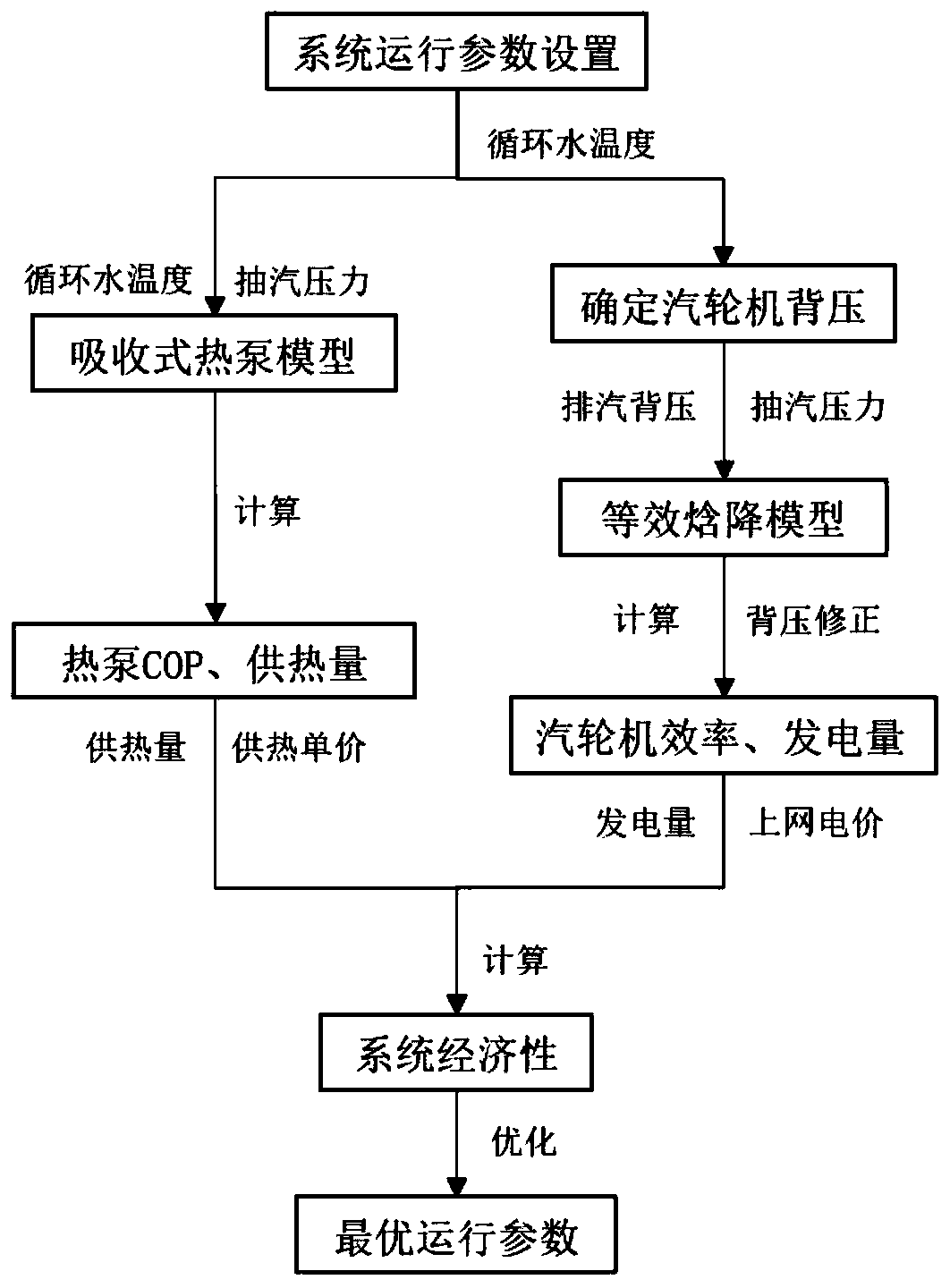
[0056] figure 1 It is a flow chart of a heat supply optimization method for a thermal power plant coupled with an absorption heat pump in Embodiment 1 of the present invention.

[0057] Such as figure 1 As shown, this embodiment provides a thermal power plant coupling absorption heat pump heat supply optimization method, which is used to realize the optimal heat supply system (thermal power plant coupling absorption heat pump system) after the thermal power plant and the absorption heat pump are coupled. The determination of economical operation parameters, the method includes the following steps:

[0058] Step 1. According to the data and operating conditions of the steam turbine in the thermal power plant, an equivalent enthalpy drop model is established. The equivalent enthalpy drop model determines the exhaust steam back pressure of the corresponding steam turbine according to different circulating water temperatures, and then uses the extraction pressure and Based on ...

Embodiment 2

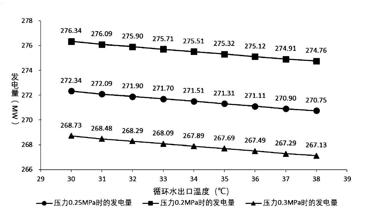
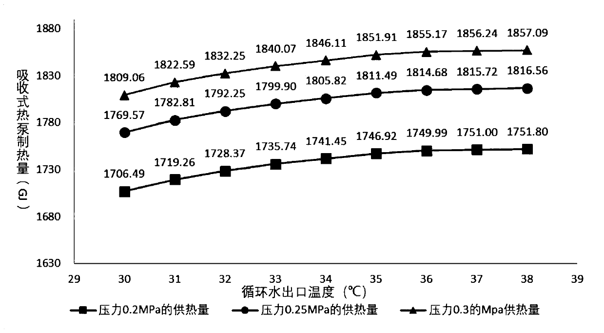
[0115] In this embodiment, a 300MW subcritical unit is taken as an example, and optimization processing (calculation) is carried out on it according to the heat supply optimization method of a thermal power plant coupled with an absorption heat pump in Embodiment 1.

[0116] In the 300MW subcritical unit of this example, under the THA working condition, the main steam pressure temperature is 16.7Mpa, 537°C, the reheat steam pressure temperature is 3.123Mpa, 537°C, the main steam flow rate is 882690kg / h, and the exhaust pressure flow rate is 4.9 kPa, 535490kg / h. The steam extraction parameters at all levels under specific THA working conditions are shown in Table 4:

[0117] Table 4. Extraction parameter table of each stage under THA working condition of 300MW unit

[0118]

[0119]

[0120] The optimization process includes:

[0121] Step 1 and 2:

[0122] According to the operating parameters of the steam turbine under the THA working condition, the fifth-stage extra...


PUM


Abstract

The invention provides a heat supply optimization method for a coupling absorption heat pump of a thermal power plant. The method comprises the following steps of 1, establishing an equivalent enthalpy drop model according to data and operation conditions of a steam turbine in the thermal power plant, determining corresponding steam exhaust back pressure of the steam turbine according to differentcirculating water temperatures by the model, and calculating the heat supply of the coupling absorption heat pump based on the steam extraction pressure and the steam exhaust back pressure, and calculating turbine efficiency and generating capacity; 2, establishing a thermal power plant cold end optimization model according to the characteristics of the steam turbine, and correcting the efficiency and the generating capacity of the steam turbine; 3, establishing an absorption heat pump model according to the property of the absorption lithium bromide heat pump, and calculating COP and heat supply after the absorption heat pump is coupled with the heat supply of the thermal power plant; and 4, setting different operating parameters (circulating water temperature and steam extraction pressure) according to the absorption heat pump waste heat recovery heat supply system, performing joint calculation through the models in the steps 1-3, and calculating the operating economy of the systemaccording to the local on-grid electricity price and the heat supply price to obtain the optimal operating parameters.

Description

technical field [0001] The invention relates to the field of thermal power plant operation optimization, in particular to a thermal power plant coupled absorption heat pump heat supply optimization method. Background technique [0002] With the vigorous development of new energy, my country has invested more and more new energy generating units such as distributed gas tri-generation, photovoltaic, wind power, and nuclear power, which has gradually reduced the proportion of traditional thermal power plants in power consumption. In such a form, small thermal power units have changed from main generating units to peak-shaving units, and some of them have even started deep peak-shaving, which will directly bring about problems such as reduced unit efficiency, equipment safety issues, and reduced unit life. Nowadays, traditional thermal power plants should find new ways of development. In some places with a large amount of stable heat demand, thermal power plants use heat supply ...

Claims


Application Information

Patent Timeline
Patent Type & Authority Applications(China)
IPC IPC(8): F24D19/10F01K13/00
CPCF01K13/00F24D19/1039F24D19/1048
Inventor 寇相斌杨涌文李琦芬宋丽斐
Owner SHANGHAI UNIVERSITY OF ELECTRIC POWER
Learn More