A vacuum sensor and test method for plateau use in new energy vehicles

A vacuum sensor and new energy vehicle technology, applied in vacuum gauges, instruments, measuring devices, etc., can solve the problems of affecting the service life of the sensor, power consumption, failure of the life of the pressure-transmitting chip, etc., and achieve high reliability and power saving. And the effect of long life and high leakage resistance

Active Publication Date: 2021-05-11
ZHEJIANG LEAPMOTOR TECH CO LTD
View PDF18 Cites 0 Cited by
  • Summary
  • Abstract
  • Description
  • Claims
  • Application Information

AI Technical Summary

Problems solved by technology

But it has the following disadvantages: the sensor is always in the normal open state, used to detect the external air pressure, which consumes power continuously, and is easy to cause the life of the pressure-transmitting chip to fail. As the core component of the vacuum sensor, the pressure chip is under pressure. After the chip is damaged, the sensor needs to be replaced as a whole, which affects the service life of the sensor

Method used


Image

  • A vacuum sensor and test method for plateau use in new energy vehicles
  • A vacuum sensor and test method for plateau use in new energy vehicles
  • A vacuum sensor and test method for plateau use in new energy vehicles

Examples


Embodiment Construction

[0023] The present invention will be further described below in conjunction with the accompanying drawings and specific embodiments.

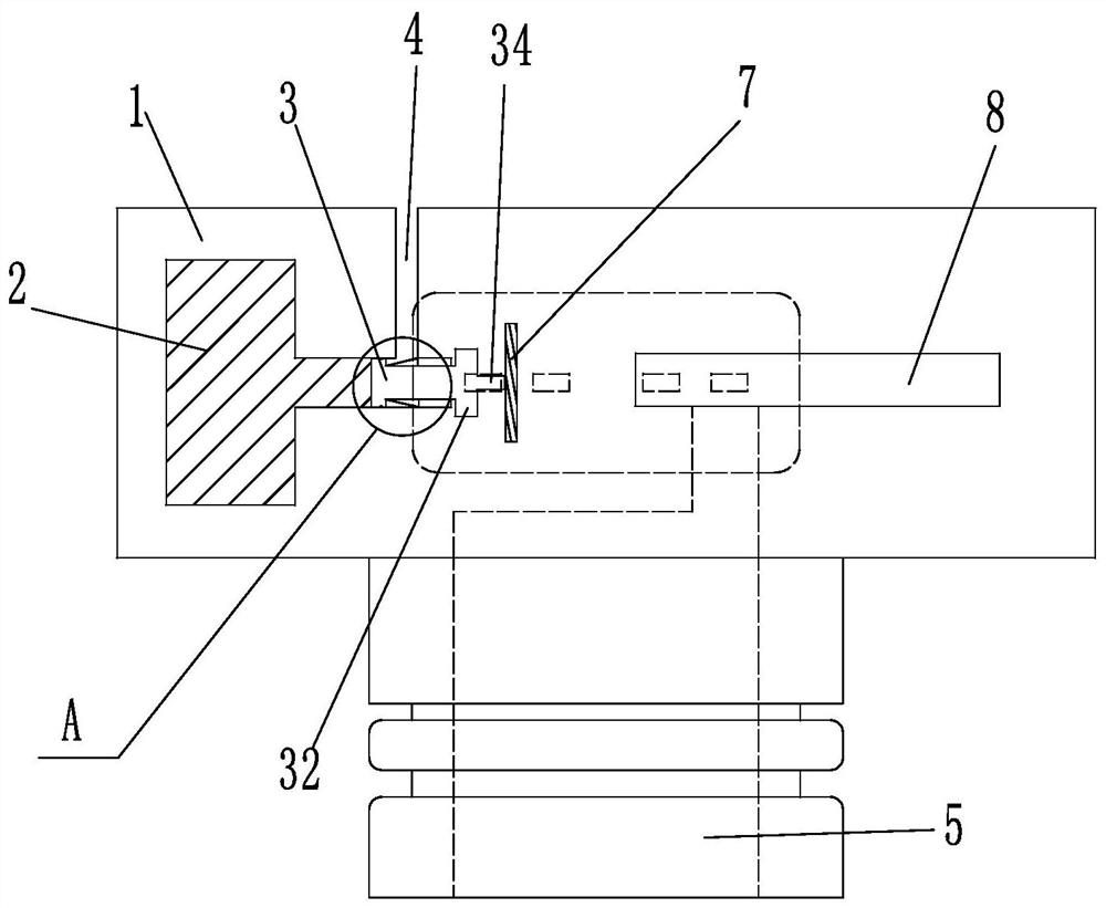
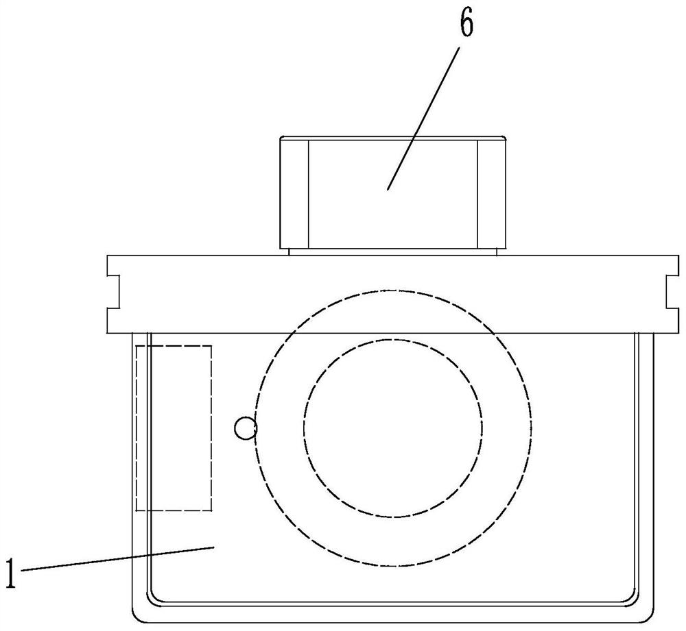
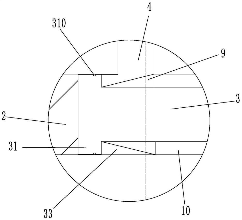
[0024] like Figure 1 to Figure 3 The illustrated embodiment is a plateau vacuum sensor for new energy vehicles, which is characterized in that it includes a housing 1 and an air chamber 2 inside the housing 1, the air chamber 2 and the outside are sealed with a piston 3, and the piston 3 It is slidably connected with the air chamber 2, and the housing 1 is provided with a slide hole matching the piston 3 on the wall of the air chamber 2, and the slide hole is a cylindrical through hole. The air chamber 2 includes a cavity with a longitudinal section of a square, the air chamber 2 is a cuboid, the sliding hole is coaxial with the air chamber 2, and the connecting section 31 of the piston 3 is located in the middle of the sliding hole. The piston 3 is provided with a connecting section 31 which slides and seals with the slide hole, and one end ...


PUM


Abstract

The invention discloses a plateau vacuum sensor and testing method for a new energy vehicle, which is characterized in that it includes a housing and an air chamber in the housing, the air chamber is sealed with the outside world with a piston, and the piston and the air chamber are slidably connected. One end of the piston is located outside the air chamber, and the outer end of the piston located outside the air chamber is provided with a differential pressure chip fixed to the housing, which can be in contact with the outer end of the piston; the housing is also provided with a pure pressure chip connected to the vacuum pump by a pipeline. The advantage of the present invention is that compared with the prior art, the present application can directly output the pressure difference between the outside world and the standard atmospheric pressure, thereby improving the response rate of the vacuum pump booster adjustment; it can identify the altitude of the plateau area; the cost is lower and the weight is lower, saving electricity and Long life; high reliability; high leakage resistance of the air chamber, smooth movement of the piston, and high system stability.

Description

technical field [0001] The invention belongs to the field of vacuum sensors for electric vehicles, in particular to a high-altitude vacuum sensor for new energy vehicles and a testing method. Background technique [0002] The electric vacuum pump control strategy is the control logic and strategy for the electric vacuum pump on the car. The electric vacuum pump is a part of the vacuum boosting system of the car. The vacuum boosting system includes: electric vacuum pump, vacuum tank, vacuum booster, vacuum pipeline and other parts. The electric vacuum pump is responsible for extracting vacuum; the vacuum tank is responsible for storing the vacuum drawn by the electric vacuum pump and collecting vacuum. degree signal, and control the direction of the vacuum; the vacuum booster is responsible for providing boost to the driver, which has enabled the driver to provide sufficient braking strength with a small pedal force, and this process consumes electric energy. Therefore, whet...

Claims


Application Information

Patent Timeline
Patent Type & Authority Patents(China)
IPC IPC(8): G01L21/00
CPCG01L21/00
Inventor 宋建勋尹浩
Owner ZHEJIANG LEAPMOTOR TECH CO LTD
Why Eureka
Try Eureka