[0045] The technical solutions in the embodiments of the present invention will be clearly and completely described below in conjunction with the accompanying drawings in the embodiments of the present invention. Obviously, the described embodiments are only a part of the embodiments of the present invention, rather than all the embodiments. Based on the embodiments of the present invention, all other embodiments obtained by a person of ordinary skill in the art fall within the protection scope of the present invention.
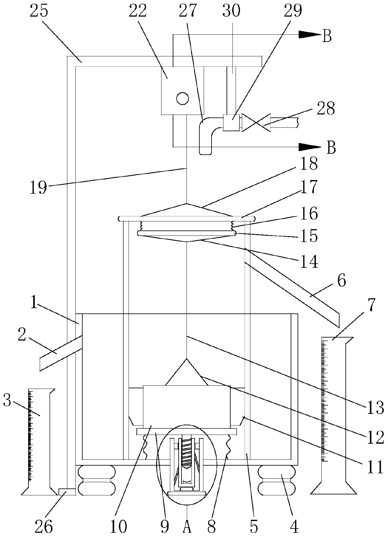
[0046] According to an embodiment of the present invention, such as figure 1 As shown, a device for measuring the permeability coefficient of permeable bricks is provided, which includes an overflow tank 1, a permeable cylinder 5, and a permeable brick body 11. The bottom plate of the overflow tank 1 is fixedly connected with a number of support columns 4, and the support columns 4 are arranged ,Used to play a supporting role. Through the supporting role of the support column 4, the overflow tank 1 can be supported away from the ground, and the height of the overflow tank 1 can be increased, so that in actual applications, the overflow tank 1 can be guaranteed to be clean , It can increase the height to achieve the effect of convenient operation. The combination structure of No. 1 measuring cylinder 3 and No. 2 measuring cylinder 7 is increased, which is used to collect overflow water, and at the same time, it has the measurement of overflow water, so that in actual work, the staff Data can be read directly to achieve the effect of efficient work, such as figure 1 As shown, in this embodiment, a No. 1 overflow pipe 2 is inserted on the side wall of the overflow tank 1, and the overflow tank 1 is connected to the outside through the No. 1 overflow pipe 2. The No. 1 overflow pipe 2 is located outside the overflow tank 1. A measuring cylinder 3 is placed directly below one end of the water tank, and the outlet of the overflow pipe 2 is set obliquely downward, so as to ensure that the overflowing water can accurately enter the measuring cylinder 3, and the outer wall of the overflow tank 1 is connected with an L-shaped The support plate 25, the L-shaped support plate 25 is welded to the outer side wall of the overflow tank 1, and the lower end of the vertical section of the L-shaped support plate 25 is connected with a fixed support 26, which is fixed on the foundation by fixing screws, The synergy of the fixing screws and the fixing support 26 can ensure that the L-shaped support plate 25 is more stable. The permeable tube 5 is arranged in the overflow tank 1, and the overflow tank 1 and the permeable tube 5 are integrally poured. No. 2 overflow pipe 6 is fixedly inserted into the side wall of 5, and the permeable tube 5 is connected to the outside through the No. 2 overflow pipe 6. The No. 2 overflow pipe 6 is located at the end of the overflow tank 1 and is provided with a No. 2 measuring cylinder 7. The outlet of the No. 2 overflow pipe 6 is also inclined downwards, such as figure 1 As shown, this can ensure that the overflowing water can accurately enter the second measuring cylinder 7.
[0047] The permeable brick body 11 is slidably arranged in the permeable tube 5. In the design, the shape of the permeable brick body 11 is set to be consistent with the shape of the cavity of the permeable tube 5, and the sizes of the two are consistent, so that the permeable brick body 11 is both It can be placed in the permeable tube 5, and the sealing between the two can be ensured, such as figure 1 As shown, and the permeable brick body 11 is arranged on the U-shaped supporting plate assembly 10. In this embodiment, the increase in the combined structure of the flat supporting plate 9 and the U-shaped supporting plate assembly 10 can provide a better effect on the permeable brick body 11. At the same time, it also has a clamping effect on the permeable brick body 11. The above-mentioned combined structure can prevent the permeable brick body 11 from shaking when moving in the permeable tube 5, thereby avoiding the permeable brick body 11 against the permeable tube 5 There is no need to hit, so as to protect the permeable cylinder 5. The U-shaped supporting plate assembly 10 is placed on the flat supporting plate 9 without any adhesion between the two. This provides a way to take the permeable brick body 11 It is convenient, and the flat support plate 9 is slidably arranged in the permeable tube 5. The lower end of the flat support plate 9 is fixedly connected to one end of several support springs 8, and the other end of the support spring 8 is fixed to the inner bottom of the overflow tank 1. On the wall, the upper end of the U-shaped supporting plate assembly 10 is fixedly connected with a pulling rope 12, the upper end of the first pulling rope 12 is fixedly connected with the lower end of the elastic pulling rope 13, and the upper end of the elastic pulling rope 13 is connected to the second The lower end of the No. 2 pull rope 14 and the upper end of the No. 2 pull rope 14 are connected to the No. 1 support ring 15. The upper end of the No. 1 support ring 15 is connected with a number of connecting springs 16, and the upper end of the connecting spring 16 is connected to the second On the lower end surface of the No. support ring 17, in this embodiment, such as figure 1 As shown, the increase in the combined structure of the supporting spring 8, the elastic pulling rope 13 and the connecting spring 16 can buffer the impact force, so that placing the permeable brick body 11 in the permeable tube 5 can avoid the permeable brick body 11 The impact on the bottom wall of the overflow tank 1 plays a role in protecting the overflow tank 1. The specific anti-collision process is as follows: manually take the permeable brick body 11 so that the permeable brick body 11 is placed in the cavity of the permeable tube 5 , And then let go of the permeable brick body 11, under the weight of the permeable brick body 11, the U-shaped supporting plate assembly 10 will move downwards. During the movement, the elastic pulling rope 13 and the connecting spring 16 are stretched , Under the self-elastic force of the elastic pulling rope 13 and the connecting spring 16, it has a buffer effect. At the same time, the downward movement of the U-shaped supporting plate assembly 10 will hit the flat supporting plate 9 and press The flat support plate 9 moves downwards, and the movement of the flat support plate 9 will compress the support spring 8 so that the elastic force of the support spring 8 can buffer the impact force. The second support ring 17 and the permeable tube 5 The upper end of the No. 2 support ring 17 is connected with the No. 3 pull rope 18, the upper end of the No. 3 pull rope 18 is connected with the lower end of the rigid pull rope 19, and the upper end of the rigid pull rope 19 is wound and connected On the spool 20, the spool 20 is fixedly sleeved on the rotating rod 21, and the rotating rod 21 is rotatably arranged on the fixed frame 22, the fixed frame 22 is connected to the L-shaped support plate 25, and one end of the rotating rod 21 is arranged on the fixed frame. The frame 22 is connected with the rotating handle 23. The specific process of taking out the permeable brick body 11 is as follows: manually rotating the rotating handle 23, the rotation of the rotating handle 23 will rotate the rotating rod 21, and the rotation of the rotating rod 21 will rotate The spool 20 is entangled, so that the steel pulling rope 19 is wound. The upward movement of the steel pulling rope 19 will pass through the No. 1 pulling rope 12, the elastic pulling rope 13, the No. 2 pulling rope 14, and the No. 1 The combination of the support ring 15, the connection spring 16, the second support ring 17, the third pull rope 18 and the U-shaped supporting plate assembly 10 moves the permeable brick body 11 to the outside of the permeable tube 5, and then completes the permeable brick body 11 Take it.
[0048] A connecting rod 30 is connected to the lower end surface of the horizontal section of the L-shaped support plate 25. The lower end of the connecting rod 30 is connected to the connecting ring 29, the connecting ring 29 is fixedly sleeved on the inlet pipe 27, and the inlet pipe 27 is provided with a valve 28, The water outlet of the water inlet pipe 27 is arranged directly above the permeable cylinder 5, and the water inlet of the water inlet pipe 27 is connected to an external pressure water source. In this embodiment, as figure 1 As shown, the purpose is to provide water. Specifically, after the permeable brick body 11 stops moving in the permeable tube 5, the valve 28 is opened to allow outside water to enter the permeable tube 5 to complete the water permeability coefficient measurement process.
[0049] There are four supporting pillars 4, and the four supporting pillars 4 are distributed in a matrix. This arrangement can play a better supporting role.
[0050] The outer fixed sleeve of the rotating handle 23 is provided with a non-slip rubber sleeve 24. In this embodiment, such as figure 2 As shown, this arrangement can not only play the anti-slip effect, but also play the role of hand protection.
[0051] The two opposite side walls of the permeable brick body 11 are provided with a fixing slot 111, and the fixing slot 111 is matched with the U-shaped supporting plate assembly 10. In this embodiment, such as Figure 5 As shown, the setting of the fixing slot 111 is used to achieve a better clamping and fixing effect. Specifically, when the U-shaped supporting plate assembly 10 is used to complete the fixing and clamping of the permeable brick body 11, it can be more effective Fix the gripping process.
[0052] In this embodiment, such as image 3 As shown, the U-shaped supporting plate assembly 10 includes a horizontal supporting plate 101 and a vertical supporting plate 103. There are two vertical supporting plates 103, and the two vertical supporting plates 103 are respectively fixedly arranged on opposite sides of the horizontal supporting plate 101. On both ends, the two vertical support plates 103 are arranged to match the fixing slot 111, so that in the actual clamping and fixing process, it can play an effective clamping and fixing function.
[0053] Preferably, the horizontal support plate 101 is provided with a plurality of No. 1 water permeable holes 102 which penetrate up and down, so as to avoid interference with the measurement result.
[0054] At the same time, both vertical support plates 103 are provided with a number of No. 2 water permeable holes 104 that penetrate right and left, so as to achieve a better effect of avoiding interference.
[0055] In order to achieve a better clamping and fixing effect, in this embodiment, the two vertical support plates 103 are provided with threaded holes 105, the internal threads of the threaded holes 105 are provided with a threaded rod 106, and the tip of the threaded rod 106 is rotated with The upper ends of the two vertical support plates 103 are provided with anti-sticking strips 108, such as Figure 4 As shown, the specific clamping process is as follows: screw the threaded rod 106, and the rotation of the threaded rod 106 will push the resisting plate 107 to move, thereby completing the clamping process of the permeable brick body 11 through the resisting plate 107.
[0056] This embodiment, such as figure 1 with Figure 7 As shown, the bottom wall of the overflow tank 1 is provided with a buffer assembly 31, and the buffer assembly 31 is connected to the lower plate of the flat support plate 9. The buffer assembly 31 includes a fixed outer barrel 311, a rotating inner barrel 312 and a threaded rod 314 The arrangement of the buffer assembly 31 can achieve a better buffer effect. The fixed outer tub 311 is fixedly inserted into the inner bottom wall of the overflow tank 1, and the open end of the fixed outer tub 311 faces upwards, and the rotating inner tub 312 is set in Inside the fixed outer barrel 311, and the rotating inner barrel 312 is provided with internal threads, the lower end of the rotating inner barrel 312 is rotatably arranged on the inner bottom wall of the fixed outer barrel 311 through the bearing 313, and the outer side walls of the rotating inner barrel 312 are connected with several One end of a rubber band 318, and the other end of the rubber band 318 is fixedly arranged on the inner side wall of the fixed outer barrel 311, the inner bottom wall of the rotating inner barrel 312 is connected with the second magnet 317, and the outer movable sleeve of the rotating inner barrel 312 is provided with a sealing sleeve 315, and the sealing sleeve 315 is fixedly arranged in the fixed outer barrel 311, the threaded rod 314 is connected to the lower plate of the flat support plate 9, and the threaded rod 314 is threadedly connected with the internal thread of the rotating inner barrel 312, the lower end of the threaded rod 314 No. 1 magnet 316 matched with No. 2 magnet 317 is provided. When designing, the opposite end of No. 1 magnet 316 and No. 2 magnet 317 is set to have the same magnetic properties. The specific buffering process is as follows: 10 When an impact occurs on the flat support plate 9, the flat support plate 9 will move downward with the threaded rod 314. Because the threaded rod 314 is threadedly connected with the internal threaded screw of the rotating inner barrel 312, the threaded rod 314 moves downwards. The movement will cause the rotating inner barrel 312 to rotate, and the rotation of the rotating inner barrel 312 will cause the rubber band 318 to be wound and stretched, so that the elastic force of the rubber band 318 can buffer the impact force. At the same time, The downward movement of the threaded rod 314 will cause the first magnet 316 to move closer to the second magnet 317. Since there is a repulsive force between the first magnet 316 and the second magnet 317, under the action of the repulsive force, it will buffer the impact force. effect.
[0057] The above are only the preferred embodiments of the present invention and are not intended to limit the present invention. Any modification, equivalent replacement, improvement, etc. made within the spirit and principle of the present invention shall be included in the protection scope of the present invention within.