Laser fiber coupling optical path structure

A fiber coupling and laser technology, applied in the field of fiber coupling, can solve the problems of low coupling efficiency of laser fiber coupling optical path, achieve good performance, improve coupling efficiency, and increase the effect of angle range

Pending Publication Date: 2020-06-09
四川京湖光电科技有限公司
View PDF0 Cites 0 Cited by
  • Summary
  • Abstract
  • Description
  • Claims
  • Application Information

AI Technical Summary

Problems solved by technology

[0003] The purpose of the present invention is to provide a laser fiber coupling optical path structure to solve the problem of low coupling efficiency of the existing laser fiber coupling optical path

Method used


Image

  • Laser fiber coupling optical path structure
  • Laser fiber coupling optical path structure

Examples


Embodiment Construction

[0014] The principles and features of the present invention are described below in conjunction with the accompanying drawings, and the examples given are only used to explain the present invention, and are not intended to limit the scope of the present invention.

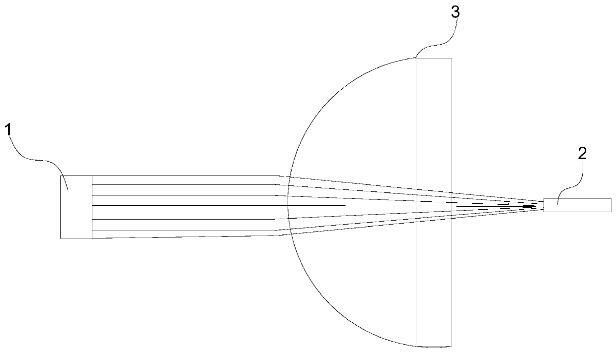
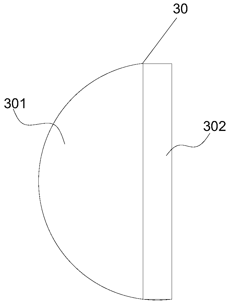
[0015] Such as Figure 1 to Figure 2 As shown, the laser fiber coupling optical path structure includes a laser generator 1, a multimode fiber 2, and a coupling optics 3 between the laser generator 1 and the multimode fiber 2, and the laser beam focused by the coupling optics 3 is focused at most The center of the mode fiber 2, and the center of the multimode fiber 2 and the center of the coupling optics 3 are located on the same optical axis.

[0016] The laser generator 1 adopts LD laser, which adopts semiconductor material as working substance, has small volume, long service life, good performance and high luminous efficiency. Multimode fiber 2 has many transmission modes and low cost. When in use, the collimat...


PUM

PropertyMeasurementUnit
diameteraaaaaaaaaa

Abstract

The invention discloses a laser optical fiber coupling optical path structure which comprises a laser generator, a multimode optical fiber and a coupling optical piece located between the laser generator and the multimode optical fiber, a laser beam focused by the coupling optical piece is focused to the center of the multimode optical fiber, and the center of the multimode optical fiber and the center of the coupling optical piece are located on the same optical axis. Use performance is good, coupling efficiency is high, a laser beam output by the laser generator is coupled into the optical fiber through the coupling optical piece; in the process, the coupling optical piece adopts a special convex surface and plane structure of the plano-convex condensing lens, so that the collimated laser beam output by the laser generator is focused through the convex surface and the plane in sequence, the coupling efficiency is effectively improved, and the use performance of a product is improved.

Description

technical field [0001] The invention relates to the technical field of optical fiber coupling, in particular to a laser optical fiber coupling optical path structure. Background technique [0002] Existing LD lasers output collimated laser beams. The spot diameter of the focused laser beam is larger than the core diameter of the fiber, so it cannot be effectively coupled into the fiber. The coupling efficiency is low, resulting in poor product performance. Contents of the invention [0003] The object of the present invention is to provide a laser fiber coupling optical path structure to solve the problem of low coupling efficiency of the existing laser fiber coupling optical path. [0004] The technical solution of the present invention to solve the above-mentioned technical problems is as follows: the laser fiber coupling optical path structure includes a laser generator, a multimode fiber, and a coupling optical part between the laser generator and the multimode fiber, ...

Claims


Application Information

Patent Timeline
Patent Type & Authority Applications(China)
IPC IPC(8): G02B6/42
CPCG02B6/4204G02B6/4228
Inventor 刘征平杨仲奎刘鹏伟
Owner 四川京湖光电科技有限公司
Why Eureka
Try Eureka