Eureka AIR delivers breakthrough ideas for toughest innovation challenges, trusted by R&D personnel around the world.

Converters and data transmission systems

A data transmission system and converter technology, applied in the field of data conversion and data transmission, can solve the problems of difficult connection and difficult to change the connection relationship of equipment.

Active Publication Date: 2021-10-22
SOCIONEXT INC
View PDF16 Cites 0 Cited by
  • Summary
  • Abstract
  • Description
  • Claims
  • Application Information

AI Technical Summary

Problems solved by technology

[0008] However, in the conventional technology described above, since the devices are fixedly connected in a one-to-one manner, it is difficult to change the connection relationship of the devices.
For example, when a BD player installed in the living room is connected to a TV set in a bedroom via HDMI via LAN, it is very easy to disconnect the connection and connect the BD player to a TV set in another bedroom. difficult

Method used


Image

  • Converters and data transmission systems
  • Converters and data transmission systems
  • Converters and data transmission systems

Examples


Embodiment approach 1

[0026] [Network Configuration of Data Transmission System]

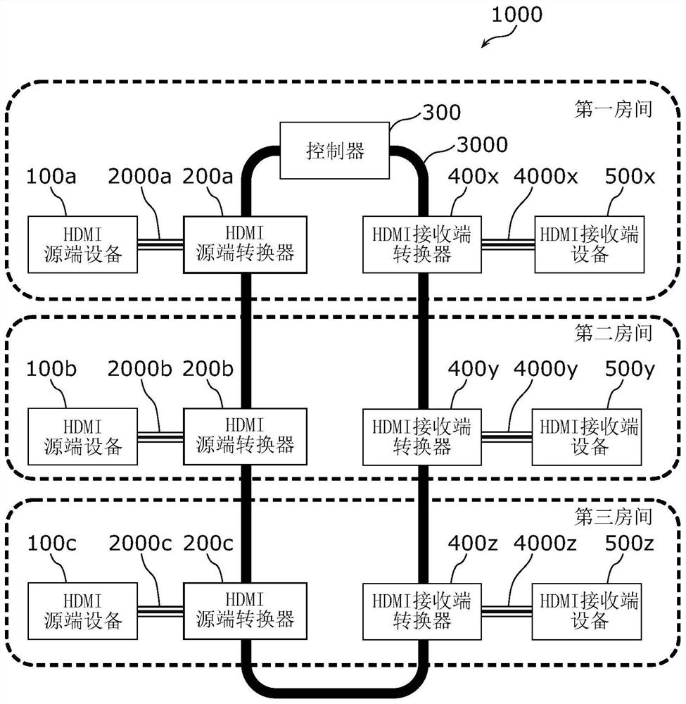
[0027] First, the network configuration of the data transmission system according to Embodiment 1 will be described. figure 1 is a network configuration diagram of the data transmission system 1000 according to Embodiment 1, as will be described later, figure 1 Shown is the state after the connected HDMI device is identified as an HDMI source (Source) device or an HDMI sink (Sink) device.

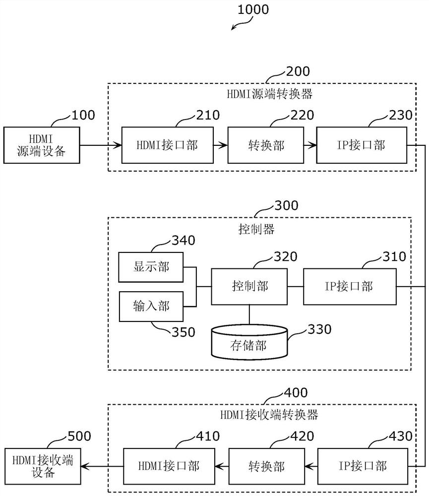
[0028] The data transmission system 1000 includes: HDMI source devices 100a, 100b, 100c; HDMI source converters 200a, 200b, 200c; controller 300; HDMI sink converters 400x, 400y, 400z; HDMI sink devices 500x, 500y, 500z.

[0029] The HDMI source devices 100a, 100b, and 100c are defined as source transmitters in the HDMI standard specification. For example, each of the HDMI source devices 100a, 100b, and 100c is a BD player, DVD player, HDD (Hard Disk Drive: Hard Disk Drive) recorder, etc., and transmits video and audio signals....

Embodiment approach 2

[0101] Next, Embodiment 2 will be described. This embodiment differs from the first embodiment described above in that power line communication (PLC) is used for network communication. In the HDMI source converter and the data transfer system according to the second embodiment, the differences from the first embodiment described above will be mainly described.


PUM


Abstract

The HDMI source converter (200) is provided with: an HDMI interface unit (210) for inputting a first signal based on the HDMI communication protocol; an IP interface unit (230) from a controller connected to a network (3000) based on the internetworking protocol (300), via the network (3000) to receive the address information on the network (3000) of the HDMI sink converter (400) different from the controller (300); The first signal of the IP interface (210) at least adds address information, so as to convert the first signal based on the HDMI communication protocol into the second signal based on the Internet interconnection protocol, and the IP interface part (230) via the network (3000), converts the second signal Send to HDMI sink converter (400).

Description

technical field [0001] The present invention relates to data conversion and data transmission between devices connected by HDMI (registered trademark) (High-Definition Multimedia Interface) and / or USB (Universal Serial Bus: Universal Serial Bus). Background technique [0002] Most audiovisual equipment, its associated equipment, and peripheral equipment are connected via HDMI / USB cables. Therefore, in order to connect devices arranged separately in a plurality of rooms, it is necessary to lay HDMI / USB cables across the rooms. [0003] Regarding the laying of HDMI / USB cables in the house, problems arise from the viewpoints of appearance and cost. For example, in order to connect a BD (Blu-ray (registered trademark) Disc) player installed in the living room to a TV installed in the bedroom, if an HDMI cable is laid along the walls of the living room and the bedroom, it will affect the The appearance of the room, if the cable is laid in the wall, the cost will increase. And,...

Claims


Application Information

Patent Timeline
Patent Type & Authority Patents(China)
IPC IPC(8): H04L12/28H04L29/06
CPCH04L12/28H04N7/106H04N21/43615H04N21/43635H04N21/64707H04L65/61H04L65/765H04N7/0125H04N7/102H04N7/12H04L65/75
Inventor 平野诚坂地亮郑凯云丸井信一
Owner SOCIONEXT INC
Why Eureka
Eureka Blog
Learn More