Four-piece optical device coupling welding equipment based on power detection

A technology for welding equipment and power detection, which is applied in the direction of laser welding equipment, welding equipment, metal processing equipment, etc., can solve the problems of affecting the packaging quality of optical devices, reducing the optical power of optical devices, and low coupling accuracy of equipment, so as to reduce packaging Low efficiency, large coupling error reduction, coupling accuracy and improved welding quality

Inactive Publication Date: 2020-06-12
CENT SOUTH UNIV
View PDF11 Cites 5 Cited by
  • Summary
  • Abstract
  • Description
  • Claims
  • Application Information

AI Technical Summary

Problems solved by technology

However, for the above-mentioned four-piece optical device, due to the need for multiple coupling alignment and welding to complete power coupling and equalization, the equipment needs to have more complex coupling degrees of freedom to ensure that each component has a high coupling accuracy. So as to ensure that after multiple couplings, the overall coupling deviation is still within an acceptable range
However, the existing optical device coupling and welding equipment usually has insufficient coupling freedom. The four-piece optical device needs to be coupled multiple times separately, the packaging efficiency is low, and the coupling accuracy of the equipment is not high, resulting in the optical device after packaging. The power is significantly reduced, which ultimately affects the packaging quality of optical devices

Method used


Image

  • Four-piece optical device coupling welding equipment based on power detection
  • Four-piece optical device coupling welding equipment based on power detection
  • Four-piece optical device coupling welding equipment based on power detection

Examples


Embodiment Construction

[0032] In order to make the technical problems, technical solutions and advantages to be solved by the present invention clearer, the following will describe in detail with reference to the drawings and specific embodiments. Apparently, the described embodiments are some, but not all, embodiments of the present invention. Based on the embodiments of the present invention, all other embodiments obtained by persons of ordinary skill in the art without making creative efforts belong to the protection scope of the present invention. In addition, the technical features involved in the different embodiments of the present invention described below may be combined with each other as long as there is no conflict with each other.

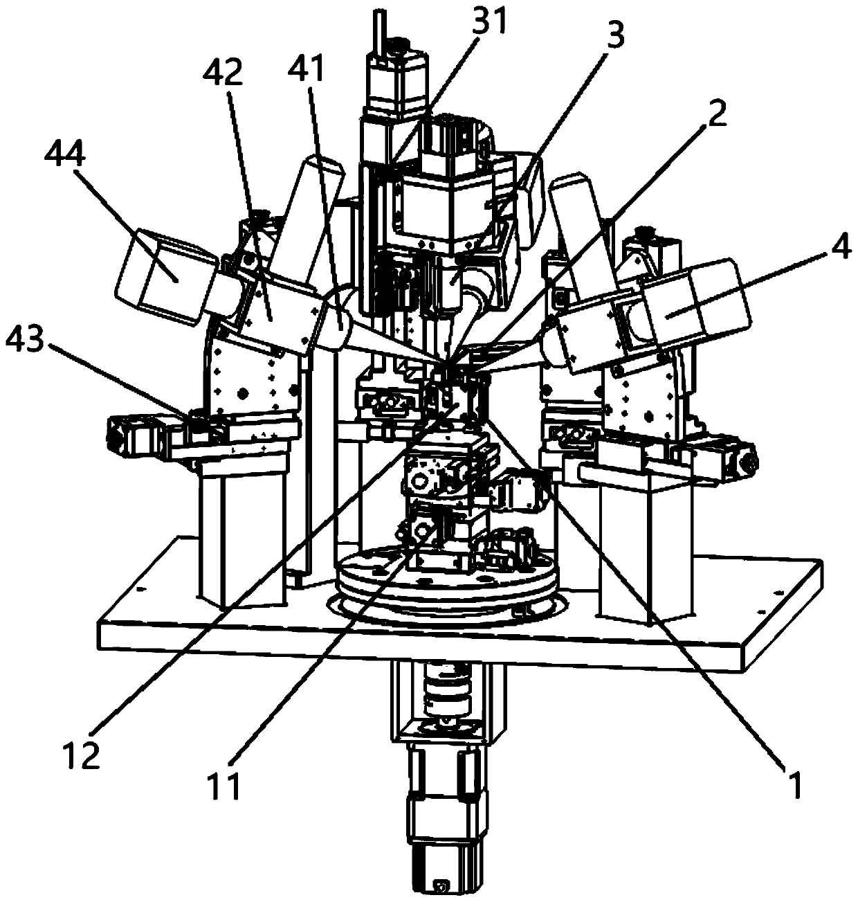
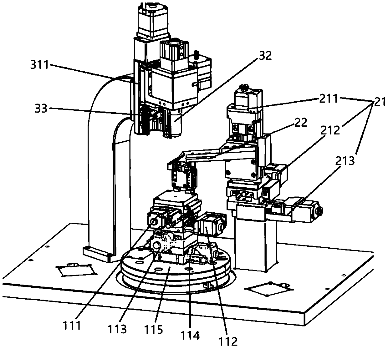
[0033] Such as figure 1 , figure 2 As shown, the embodiment of the present invention provides a four-piece optical device coupling welding equipment based on power detection, including a lower clamp assembly 1 for clamping a light-emitting device 01, a le...


PUM


Abstract

The invention provides four-piece optical device coupling welding equipment based on power detection. The equipment comprises a lower clamp assembly for clamping a light emitting device, a lens clampassembly for clamping a lens, an upper clamp assembly for clamping a receiving device and an adjustment ring and a plurality of sets of welding devices for laser welding, wherein the lower clamp assembly comprises a lower clamp motion platform and a lower clamp disposed on the lower clamp motion platform, the lens clamp assembly comprises a lens clamp motion platform and a lens clamp disposed on the lens clamp motion platform, and the upper clamp assembly comprises an upper clamp motion platform, a receiving device clamp for clamping the receiving device disposed on the upper clamp motion platform and an adjustment ring jacking clamp for jacking the adjustment ring. According to the equipment, the packaging process combining a plurality of coupling and a plurality of welding on a set of equipment is realized, the problems of low packaging efficiency and large coupling error caused by the plurality of coupling among elements are solved, and significant improvement is achieved relative to the prior art.

Description

technical field [0001] The invention relates to the technical field of automatic coupling and packaging of optical devices, in particular to a four-piece optical device coupling and welding equipment based on power detection. Background technique [0002] With the development of optical fiber communication and optical fiber sensing technology, the preparation of optical transceivers has become the key to the progress of optical information technology. In optical communication products, the demand for optical transceivers such as TOSA-laser emitting devices and BOSA-single-fiber bidirectional products (integrated sending and receiving) is increasing with the development, and its function is mainly to realize the photoelectric conversion of signals. A four-piece optical device is mainly composed of a light emitting component + a lens + a receiving component + an adjustment ring. The main process of its packaging is to first couple and align the light emitting component and the...

Claims


Application Information

Patent Timeline
Patent Type & Authority Applications(China)
IPC IPC(8): B23K26/21B23K26/08B23K26/06B23K26/70
CPCB23K26/0648B23K26/0861B23K26/0869B23K26/21B23K26/702B23K26/705
Inventor 段吉安徐聪唐佳卢胜强
Owner CENT SOUTH UNIV
Why Eureka
Try Eureka