Steel mesh hollow component with supporting points

A technology for stenciling and supporting points, which is applied in the processing of building components, building structures, and building materials, etc., can solve problems such as affecting the normal use of construction equipment, changing the strength of concrete structures, and blocking the pipelines of cast-in-place concrete delivery pumps.

Pending Publication Date: 2020-06-12
HUNAN BDF ENERGY SAVING TECH +2
View PDF3 Cites 0 Cited by
  • Summary
  • Abstract
  • Description
  • Claims
  • Application Information

AI Technical Summary

Problems solved by technology

[0003] However, there are still problems to be perfected in the original application of reticulated box-shaped components. The inventor has continuously improved the background technology of cast-in-place hollow floors and invented a double-layer structure composed of ribbed steel mesh body, support body and sealing body. ZL201721318739.2 is a hollow body member with curved surface and network shape; the combined network box-shaped member is improved and the combination of pure steel materials is used to further improve industrialization, and at the same time solve the production combination and use functions, and effectively monitor the concrete collapse If the slump is too large, there will be hidden dangers in the qual

Method used


Image

  • Steel mesh hollow component with supporting points
  • Steel mesh hollow component with supporting points
  • Steel mesh hollow component with supporting points

Examples


Embodiment Construction

[0018] The present invention will be further described below in conjunction with the accompanying drawings.

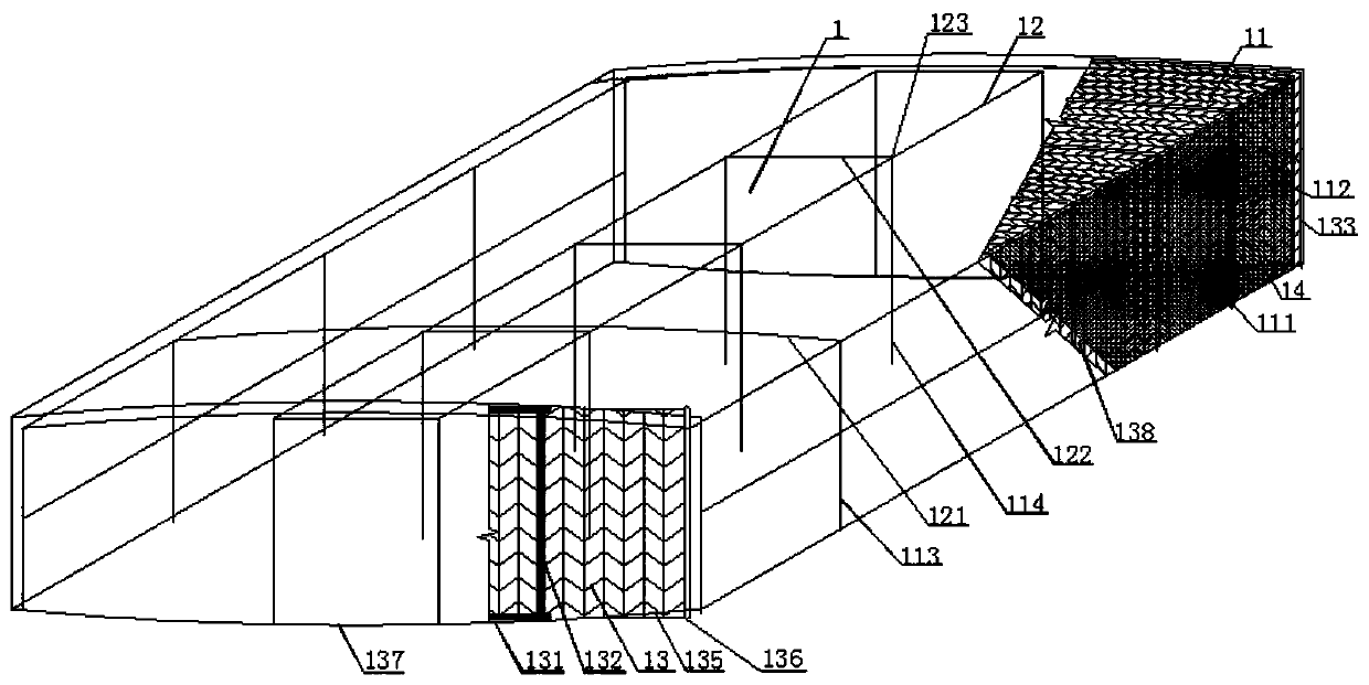
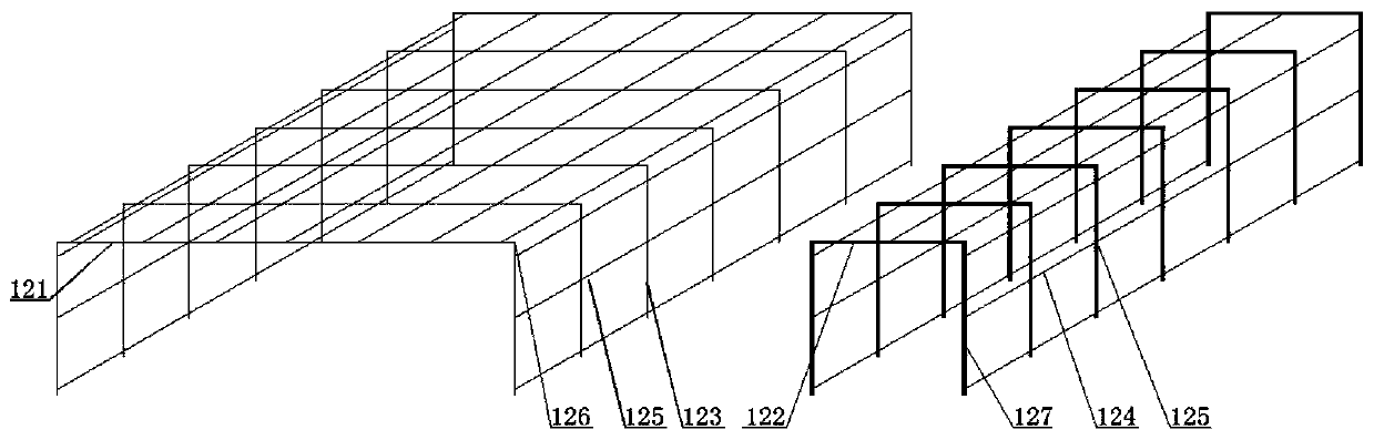
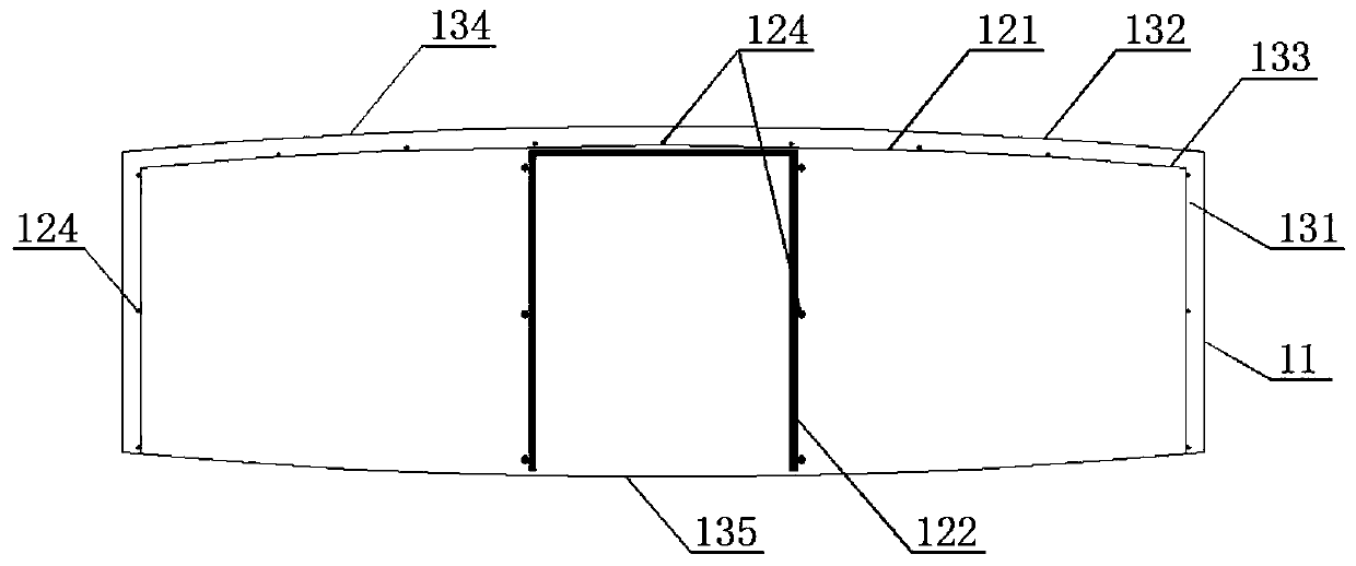
[0019] figure 1It is an embodiment of a stenciled member with supporting points of the present invention. When the present invention is implemented, according to the requirements of the function of the stenciled member 1, the ribbed steel mesh 11, the composite laminated support frame 12, and the short plug are first made. The web 13 and the non-woven fabric 14 are reeled; the ribs of the ribbed steel mesh 11 with ribs 111 and connecting pieces 112 are horizontally pressed with two cuts to control the width according to the required specifications to control the width and the height with two cuts 50mm of overlap is reserved at both ends of the ribbed steel mesh; the composite laminated support frame is divided into wide groups 121 to form width 113 and narrow groups 122 to form height 114; Wire-drawing equipment, cold-drawing the coiled steel wire into a cold-drawing ...


PUM


Abstract

The invention provides a steel mesh hollow component with supporting points. The steel mesh hollow components with the supporting points comprises a ribbed steel mesh, a folding supporting frame, an end cap short mesh, the supporting points and non-woven fabric, wherein the ribbed steel mesh is a rhombic steel mesh and is used as a steel mesh hollow component body. Reinforcing steel sheets are additionally arranged at the two ends of the end cap short mesh, and the length of the reinforcing steel sheets is smaller than the width of the end cap short mesh. The portions, not additionally provided with the reinforcing steel sheets, of the end cap short mesh are exposed out of the four outer corners of the lower bottom of the steel mesh hollow component. Ribs of the exposed end cap short meshform the supporting points at the four corners of the lower bottom of the steel mesh hollow component. The non-woven fabric is wound on the lateral surface of the steel mesh hollow component.

Description

technical field [0001] The invention relates to a system technology of a cast-in-place concrete cavity floor, in particular to a technology of a steel mesh hollow member with supporting points. Background technique [0002] For example, in order to realize the industrial production of the non-core-pulling hole-forming components of the cast-in-place hollow floor, the inventor pioneered the use of steel reticulated materials instead of plate bodies to manufacture the non-core-pulling hole-forming components of the cast-in-place hollow floor. On the basis of the hole-forming components of the original plate body, the invention and application of "a reticulated box-shaped component for forming holes in the cast-in-place hollow floor" ZL201310332173.9 and ZL201510331724.X "a new type of steel-concrete composite cast-in-place hollow floor ", transform and upgrade the existing pouring hollow floor technology, and create conditions for replacement; the application of reticulated bo...

Claims


Application Information

Patent Timeline
IPC IPC(8): E04B5/32E04G21/02
CPCE04B5/32E04G21/02
Inventor 王本淼王海崴
Owner HUNAN BDF ENERGY SAVING TECH
Why Eureka
Try Eureka