Bistable MEMS security device with inertia delay function

A bistable, inertial technology, applied in microstructure devices, coupling of optical waveguides, components of TV systems, etc., can solve the problem of limited inertial force, lack of redundant design, MEMS security devices difficult to meet design requirements, etc. problems, to achieve the effect of improving the effect and improving the safety

Active Publication Date: 2020-06-12
XI AN JIAOTONG UNIV
View PDF4 Cites 0 Cited by
  • Summary
  • Abstract
  • Description
  • Claims
  • Application Information

AI Technical Summary

Problems solved by technology

[0003] The characteristic size of MEMS security devices is generally at the micron level. In this tiny scale, the effect of inertial force is very limited. Therefore, MEMS security devices are usually controlled by electrical signals (piezoelectric, magnetoelectric, electrostatic, thermoelectric, etc.), Lack of redundant design for release by inertial force, it is difficult for a MEMS security device that relies on electrical signals to release security to meet the existing design requirements for multi-physics release, that is, the GJB-373 design criteria

Method used


Image

  • Bistable MEMS security device with inertia delay function
  • Bistable MEMS security device with inertia delay function
  • Bistable MEMS security device with inertia delay function

Examples


Embodiment Construction

[0028] The present invention will be further described below in conjunction with the embodiments and accompanying drawings.

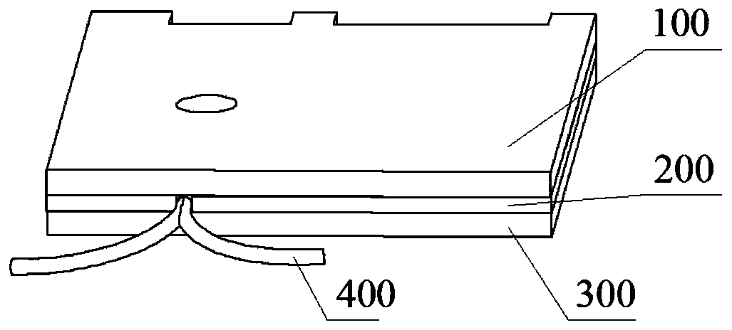
[0029] refer to figure 1 , a bistable MEMS security device with inertial delay function, the overall structure is a stacked layer, from top to bottom are the cover layer 100, the isolation layer 200 and the detonation layer 300, and the adjacent layers are bonded by gold-gold The connection is realized; the isolation layer 200 is connected to the Y-shaped optical fiber 400 by bonding, the isolation layer 200 and the Y-shaped optical fiber 400 are located on the same plane, and the Y-shaped optical fiber 400 is used to monitor the internal state of the isolation layer 200 .

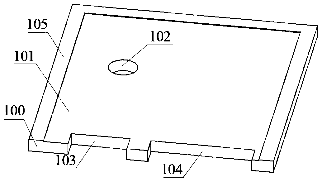
[0030] refer to figure 2 , the cover layer 100 includes a cover substrate 101, a detonation hole 102 is provided near the center of the cover substrate 101, a control electrode window 104 and a detonation electrode window 103 are provided on the long side of the cover substrate 10...


PUM


Abstract

A bistable MEMS security device with an inertia delay function is integrally of a lamination structure, a cover plate layer, a separation layer and a detonation layer are sequentially arranged from top to bottom, and the adjacent layers are connected in a metal-metal bonding manner. The separation layer is connected with Y-shaped optical fiber in an adhesion bonding manner. The separation layer and the Y-shaped optical fiber are located on the same plane, and the Y-shaped optical fiber is used for achieving monitoring of the inner state of the separation layer. A large-mass separation plate mechanism is designed in the bistable MEMS security device, and the action effect of inertia force in the MEMS security device is improved; considering the gun muzzle emitting safety distance, an inertia delay mechanism composed of a gear-rack-plane torsion spring mechanism is designed, and safety during weapon launching is improved; a bistable triggered electric heat driving mechanism is designed,and multi-physics field security releasing redundancy design is achieved; an optical fiber sensor is designed, and real-time monitoring of the interior motion state of the mechanism is achieved; and the characteristics of inertia delay, bistable triggering, state self-sustaining, state self-checking, overload resisting and the like are achieved.

Description

technical field [0001] The invention relates to the technical field of security devices, in particular to a bistable MEMS security device with an inertial delay function. Background technique [0002] Security devices are the core components that control the energy transfer of weapon systems (that is, they are used to trigger normal detonation and prevent accidental detonation). have a major impact on the future. Because traditional security devices are difficult to make breakthroughs in terms of driving methods and structural dimensions, they cannot meet the development requirements of the new generation of weapons for miniaturization, integration, and intelligence. Considering that the MEMS process has high process flexibility at the micro scale, the concept of MEMS security device came into being. [0003] The characteristic size of MEMS security devices is generally at the micron level. In this tiny scale, the effect of inertial force is very limited. Therefore, MEMS s...

Claims


Application Information

Patent Timeline
Patent Type & Authority Applications(China)
IPC IPC(8): F42C15/40B81B7/02
CPCB81B7/02F42C15/40
Inventor 胡腾江赵玉龙任炜
Owner XI AN JIAOTONG UNIV
Why Eureka
Try Eureka