Automatic control device of power isolation switch

A technology of automatic control device and isolating switch, which is applied in the direction of circuit devices, automatic disconnection emergency protection devices, emergency protection circuit devices, etc., can solve the problems of providing safety guarantees and being unable to provide electrical equipment, and achieve good application prospects Effect

Active Publication Date: 2020-06-12
山西美锦迎凯智能科技有限公司
View PDF9 Cites 4 Cited by
  • Summary
  • Abstract
  • Description
  • Claims
  • Application Information

AI Technical Summary

Problems solved by technology

[0004] In order to overcome the limitations of the structure of the existing power isolating switch, it only has the function of power supply or power off, and can only manually control the opening and closing of the power supply line, and cannot automatically disconnect the power supply when the power supply phase is missing or the phase voltage is unbalanced. The power supply of the equipment cannot provide safety guarantee for the electrical equipment. The invention provides that the operator can control the opening and closing action of the power isolating switch body by pressing the power switch on the ground, which brings convenience to the operator. , under the joint action of the phase loss monitoring circuit and the phase voltage balance circuit, as long as any phase loss or phase voltage imbalance of one transmission line of the power supply line, the control circuit can automatically disconnect the knife switch of the power isolating switch body, and in After the power supply line returns to normal, it can automatically close the knife switch of the power isolating switch body and restore the power supply of the electrical equipment, thereby achieving an automatic control of the electrical isolating switch that can protect the electrical equipment and has intelligent control functions. device

Method used


Image

  • Automatic control device of power isolation switch
  • Automatic control device of power isolation switch
  • Automatic control device of power isolation switch

Examples


Embodiment Construction

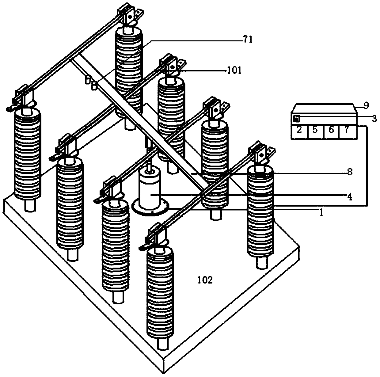
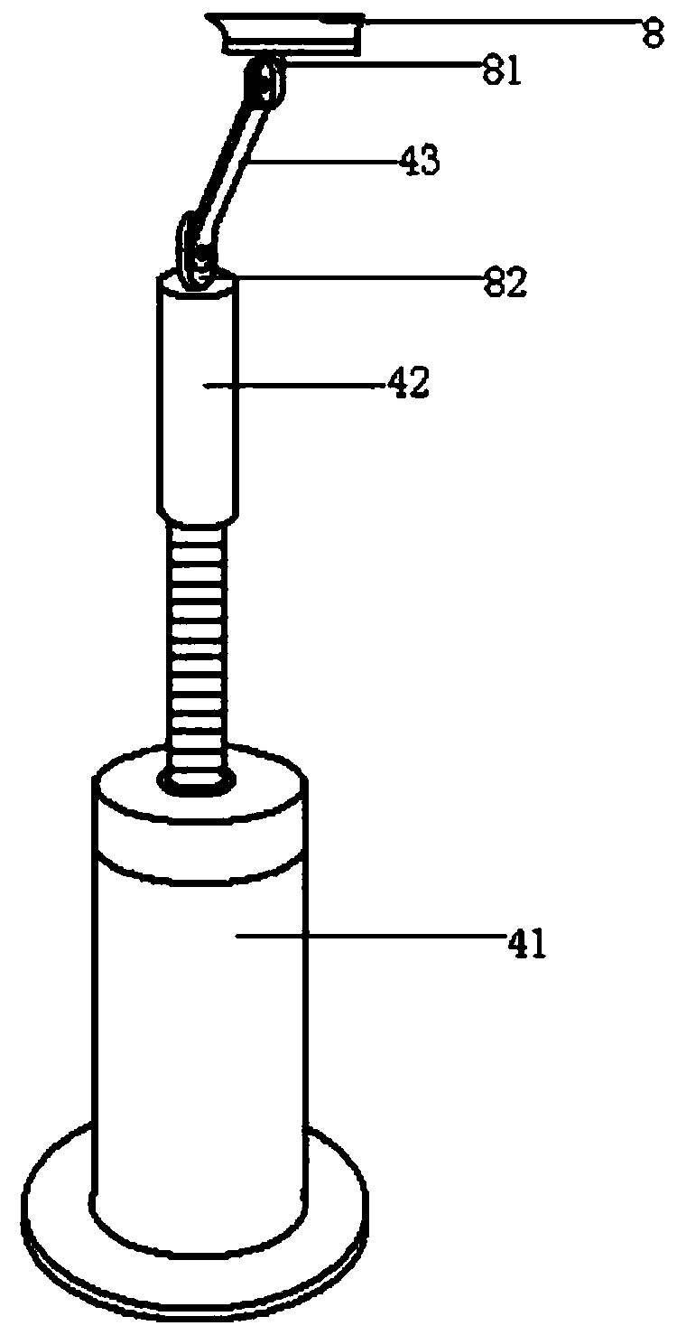
[0020] figure 1 , 2 As shown, a power isolation switch automatic control device includes a switching power supply 2, a control power switch 3, and also has an electric opening and closing mechanism 4, a phase loss monitoring circuit 5, a phase voltage balance circuit 6 and a control circuit 7; The opening and closing mechanism 4 includes a motor deceleration mechanism 41, an internal threaded pipe 42, a connecting plate 43 with shaft holes at the upper and lower ends, and a rectangular ceramic insulating material connecting rod is installed horizontally on the lower ends of the four knife gates 101 of the power isolating switch body. 8. The lower end of the housing of the motor reduction mechanism 41 is installed on the middle part of the support plate 102 of the power isolating switch body through the screw nut; the middle part of the lower end of the connecting rod 8 is longitudinally distributed with an upper support seat plate 81 (and connecting rod 8 integrally formed), ...


PUM


Abstract

An automatic control device for a power isolation switch comprises a switching power supply, a control power supply switch, an electric opening and closing mechanism, an open-phase monitoring circuit,a phase voltage balancing circuit and a control circuit; the electric opening and closing mechanism comprises a motor speed reduction mechanism, an internal threaded pipe and a connecting plate. A disconnecting link of a power disconnecting switch body is provided with a connecting rod, a motor speed reducing mechanism is installed on a supporting plate, an inner threaded pipe is installed on a power output shaft of the motor speed reducing mechanism, a lower supporting seat plate is arranged on the inner threaded pipe, and the upper end and the lower end of the connecting rod are hinged to the connecting rod and the lower supporting seat plate respectively. The switching power supply, the open-phase monitoring circuit, the phase voltage balancing circuit, the control circuit and the power switch are installed in the element box and connected with the motor speed reducing mechanism through wires. According to the invention, the switching-on and switching-off actions can be controlledon the ground, the disconnecting link of the power isolating switch body can be automatically switched off as long as any one power transmission line is open-phase or unbalanced in voltage, the disconnecting link can be automatically switched off after a power supply line is recovered, and power supply of electric equipment is recovered.

Description

technical field [0001] The invention relates to the field of electrical control equipment, in particular to an automatic control device for a power isolation switch. Background technique [0002] Power isolating switches are widely used on power supply lines (such as factory power supply lines, etc.), and play the function of turning on and off the power supply. In the actual application of the existing power isolating switch, when controlling the closing and opening of the power isolating switch, it mainly relies on manual control of the opening and closing action through the operating rod on the ground (the long length of the control rod will bring troubles to the operator. Inconvenient, time-consuming and labor-intensive operation, and inconvenient to carry). In electrical equipment, the unbalanced phase voltage and lack of phase of the three-phase power supply will affect the normal use of electrical equipment (such as motors), and even cause damage to electrical equipm...

Claims


Application Information

Patent Timeline
Patent Type & Authority Applications(China)
IPC IPC(8): H01H31/04H02H3/06
CPCH01H31/04H02H3/066
Inventor 许海青
Owner 山西美锦迎凯智能科技有限公司
Why Eureka
Try Eureka