
Method for temperature control of component

A temperature control and component technology, which is applied in the direction of temperature control using digital devices, temperature control using electric means, photoengraving process of patterned surface, etc. question

Active Publication Date: 2020-06-12
CARL ZEISS SMT GMBH
View PDF7 Cites 0 Cited by
  • Summary
  • Abstract
  • Description
  • Claims
  • Application Information

AI Technical Summary

Problems solved by technology

[0006] A problem that actually arises when using replacement parts (for example in this measurement method) is the high sensitivity of the measurement results to temperature variations, where the temperature needs to be controlled to a few millikelvin in order to achieve the desired measurement accuracy
However, the realization of such precise temperature control is a severe challenge in practice.
One reason for this is that, in general, replacement parts for amperometric procedures come from a single holder holding several different replacement parts and are transferred to the actual measurement system or the housing containing it, where the associated system (a The corresponding thermal adaptation of the cage on the one hand and the measuring system on the other hand) is made more difficult due to the thermal load present on both sides and possibly also subject to temporal fluctuations
[0007] Furthermore, after completing the transfer of the respective replacement part into the measuring system, its approach to the respective target temperature usually takes place within a period of several hours due to the relevant time constants, with the result that after obtaining a sufficiently high temperature of the relevant replacement part Relatively long time is required before temperature stabilization
[0008] However, insufficient temperature stability of replacement parts leads to undesired changes in optical properties, such as thermally induced refractive index changes and mechanical drift effects in the measurement setup, and thus ultimately to measurement errors
[0009] In practical terms, the impairment of the temperature stability of the replacement part and the related above-mentioned problems may also be due to the fact that the replacement part is usually also exposed to thermal loads during its transfer to the measurement system (i.e. on the way there)

Method used


Image

  • Method for temperature control of component
  • Method for temperature control of component
  • Method for temperature control of component

Examples


Embodiment Construction

[0036] first, Figure 6 A schematic diagram of a projection exposure apparatus is shown, which is given by example and designed for operation in the EUV range.

[0037] according to Figure 6 , the illumination device in the projection exposure apparatus 10 designed for EUV includes a field facet mirror 3 and a pupil facet mirror 4 . Light from a light source unit comprising a plasma light source 1 and a collector mirror 2 is directed to a field facet mirror 3 . The first telescopic mirror 5 and the second telescopic mirror 6 are arranged downstream of the pupil facet mirror 4 in the optical path. A deflection mirror 7 is arranged downstream in the light path and directs the radiation incident thereon to an object field in the object plane of the projection lens comprising six mirrors 21-26. At the position of the object field, a reflective structure bearing mask 31 is arranged on the mask table 30, and the mask is imaged to the image plane with the assistance of the projec...


PUM


Abstract

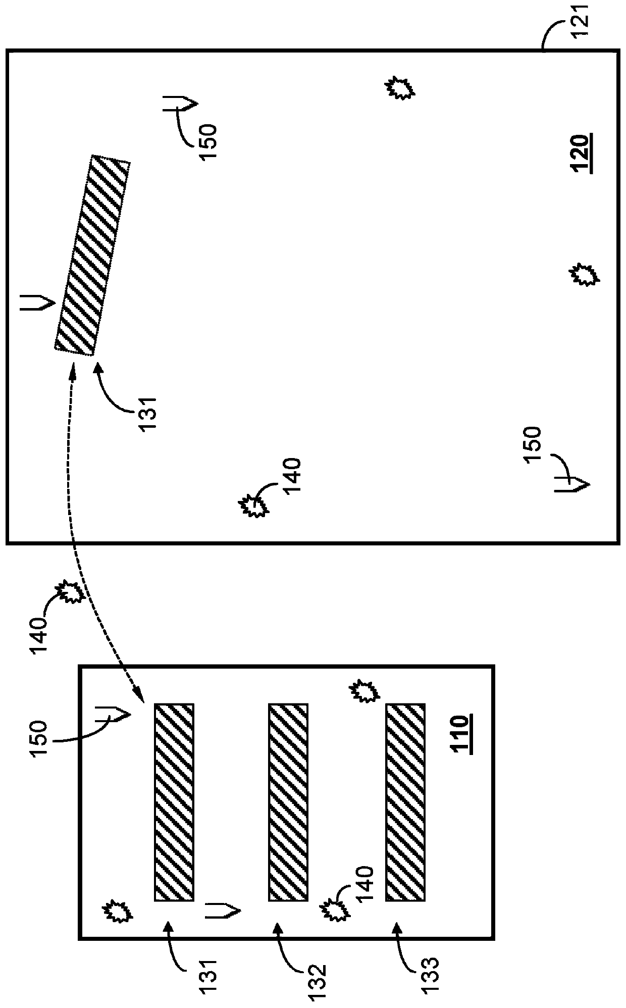
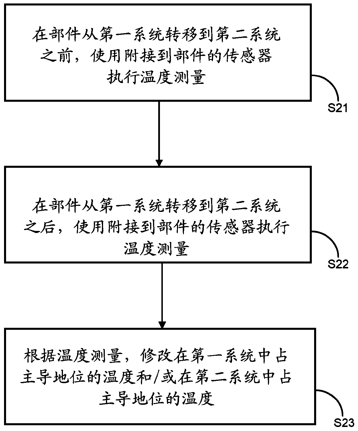
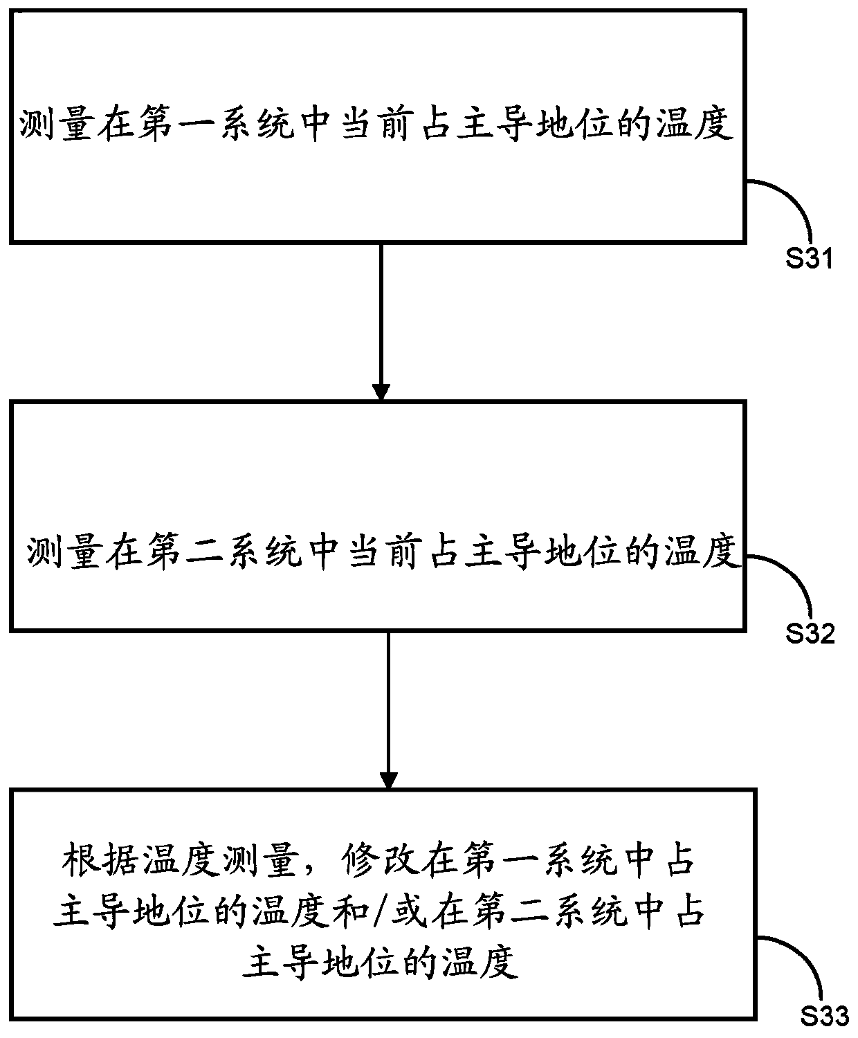
The invention relates to a method for temperature control of a component, wherein said component is transferable between a first system and a second system. In accordance with an aspect, the method includes the following steps: ascertaining a temperature drift of a temperature of the component (131) that is to be expected after transfer of the component (131) from the first system (110) into the second system (120); and modifying a temperature prevailing in the first system (110) and / or a temperature prevailing in the second system (120) such that the temperature drift that is actually occurring after transfer of the component (131) from the first system (110) into the second system (120) is reduced with respect to the expected temperature drift.

Description

[0001] Cross References to Related Patents [0002] This application claims the priority of German patent application DE 10 2017 219 151.1 filed on October 25, 2017 and German patent application DE 10 2018 201 320.9 filed on January 29, 2018. The contents of these applications are incorporated herein by reference. technical field [0003] The invention relates to a method of temperature control of a component, wherein the component is transferable between a first system and a second system. In particular, the invention can be advantageously implemented in applications where the aim is to regulate temperature-sensitive components to a reference temperature that is kept as constant as possible, or when the aim is to avoid, or at least reduce, the transfer of components to different systems or compartments. temperature drift problem. Background technique [0004] Microlithography is used to manufacture microstructural components such as integrated circuits or LCDs. The micro...

Claims


Application Information

Patent Timeline
IPC IPC(8): G03F7/20G05D23/19H01L21/67
CPCG05D23/1917G03F7/70875H01L21/67248G03F7/70741G03F1/84G02B7/008G02B7/1815G03F7/70825G03F7/705
Inventor J.洛夫H.克雷迪特T.劳弗
Owner CARL ZEISS SMT GMBH
Learn More