Motor, fan, electric vacuum cleaner, and hand drying device
A technology for motors and rotors, which is applied in the field of electric vacuum cleaners, hand dryers, and blowers. It can solve problems such as the inability to determine the rotation of the rotor, and achieve the effect of suppressing the increase of magnetic flux density and reducing iron loss.
- Summary
- Abstract
- Description
- Claims
- Application Information
AI Technical Summary
Problems solved by technology
Method used
Image

Examples
Embodiment approach 1
[0033]
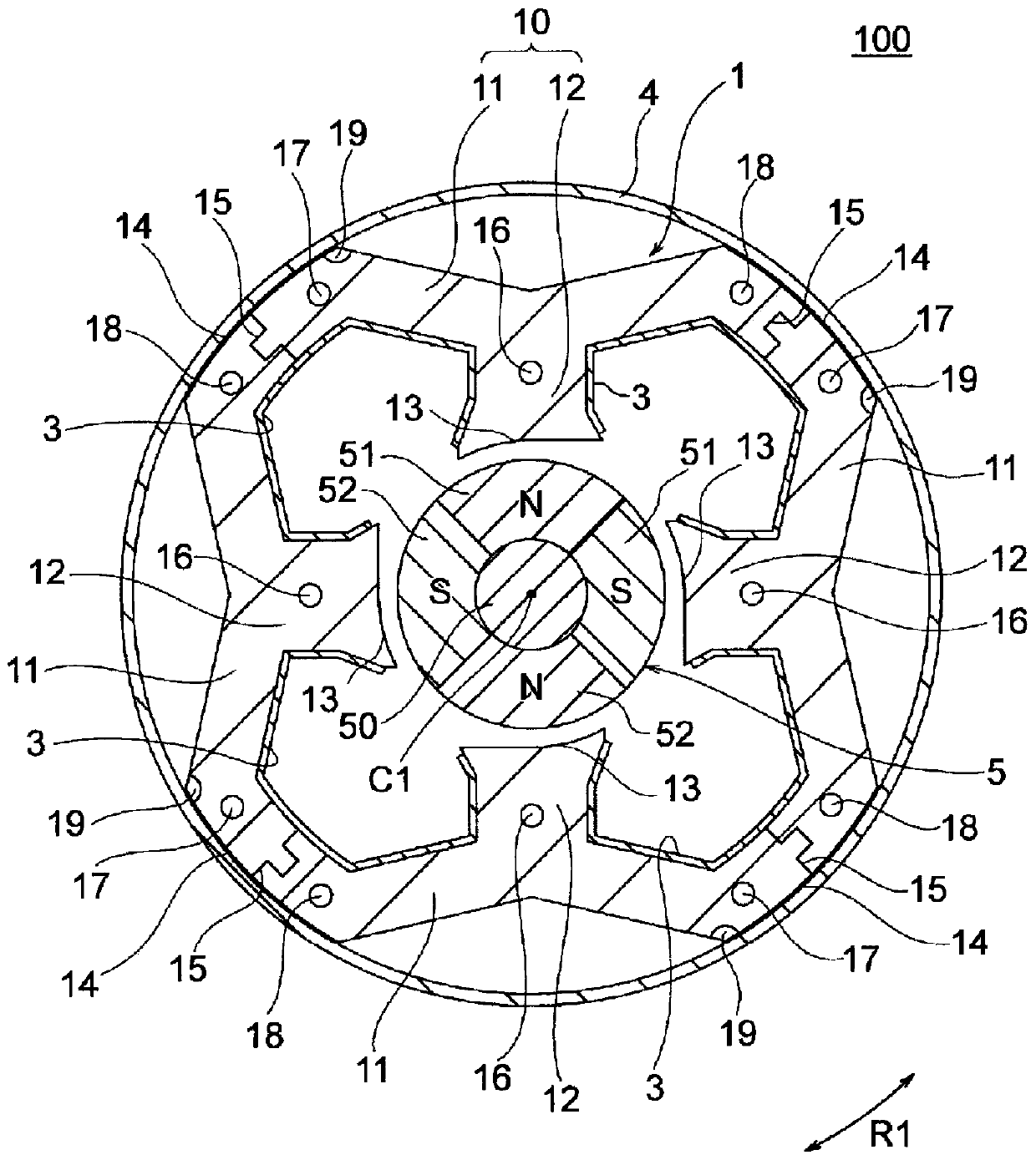
[0034] figure 1 It is a sectional view showing the motor 100 according to Embodiment 1 of the present invention. The motor 100 is a permanent magnet synchronous motor, which is a single-phase motor driven by an inverter. The motor 100 is used, for example, in a blower 110 of an electric vacuum cleaner or a hand dryer (refer to Figure 13 ).
[0035] The motor 100 has: a rotor 5 having a shaft 50 ; and a stator 1 arranged to surround the rotor 5 . The stator 1 is fixed inside a metal cylindrical frame 4 .
[0036] In the following description, the direction of the rotation axis C1 which is the central axis of the shaft 50 is referred to as "axial direction". In addition, the circumferential direction centered on the rotation axis C1 of the shaft 50 (in figure 1 etc. shown by arrow R1) is called "circumferential direction". In addition, the radial direction centering on the rotation axis C1 of the shaft 50 is referred to as "radial direction". In addition, th...
Embodiment approach 2
[0100] Next, Embodiment 2 of the present invention will be described. A motor 100A according to Embodiment 2 includes a rotor 5A having a shaft 50A, and a stator 1A surrounding the rotor 5A. Stator 1A is fixed to the figure 1 The inner peripheral side of the frame 4 is shown. In Embodiment 2, the number of magnetic poles of the rotor 5A is two, and the yoke 11A of the stator 1A is annular.
[0101] The rotor 5A has a shaft 50A and permanent magnets 51A and 52A fixed around the shaft 50A. The rotor 5A has two poles and has one permanent magnet 51A and one permanent magnet 52A.
[0102] The stator 1A has a stator core 10A, an insulating part 3 ( figure 1 ) and coils. The stator core 10A is formed by stacking a plurality of laminated elements (for example, electrical steel sheets, etc.) in the axial direction and fixing them integrally by caulking portions 16A, 17A, and 18A.
[0103] The stator core 10A has an annular yoke 11A surrounding the rotor 5A, and a plurality of ...
PUM
 Abstract
Description
Claims
Application Information
 - Generate Ideas
- Intellectual Property
- Life Sciences
- Materials
- Tech Scout
- Unparalleled Data Quality
- Higher Quality Content
- 60% Fewer Hallucinations
Browse by: Latest US Patents, China's latest patents, Technical Efficacy Thesaurus, Application Domain, Technology Topic, Popular Technical Reports.
© 2025 PatSnap. All rights reserved.Legal|Privacy policy|Modern Slavery Act Transparency Statement|Sitemap|About US| Contact US: help@patsnap.com