Belt material flow control system

A flow control system and material technology, applied in conveyor control devices, conveyor objects, transportation and packaging, etc., can solve problems such as increased belt wear, increased labor costs, inability to comprehensively and continuously measure material forms, etc., to reduce Belt wear and energy saving effect

Inactive Publication Date: 2020-06-16
BEIJING JINDE CHUANGYE CONTROL TECH
View PDF9 Cites 10 Cited by
  • Summary
  • Abstract
  • Description
  • Claims
  • Application Information

AI Technical Summary

Problems solved by technology

[0003] At present, the control method of belt material flow is mainly through manual inspection, installation of deviation switch, material flow switch and other technologies, but because most of the on-site environment is relatively harsh, and the belt is in a high-speed running state, traditional measurement methods, such as: laser Measurement, s

Method used


Image

  • Belt material flow control system
  • Belt material flow control system
  • Belt material flow control system

Examples


Embodiment Construction

[0045] First of all, those skilled in the art should understand that these embodiments are only used to explain the technical principles of the present invention, and are not intended to limit the protection scope of the present invention.

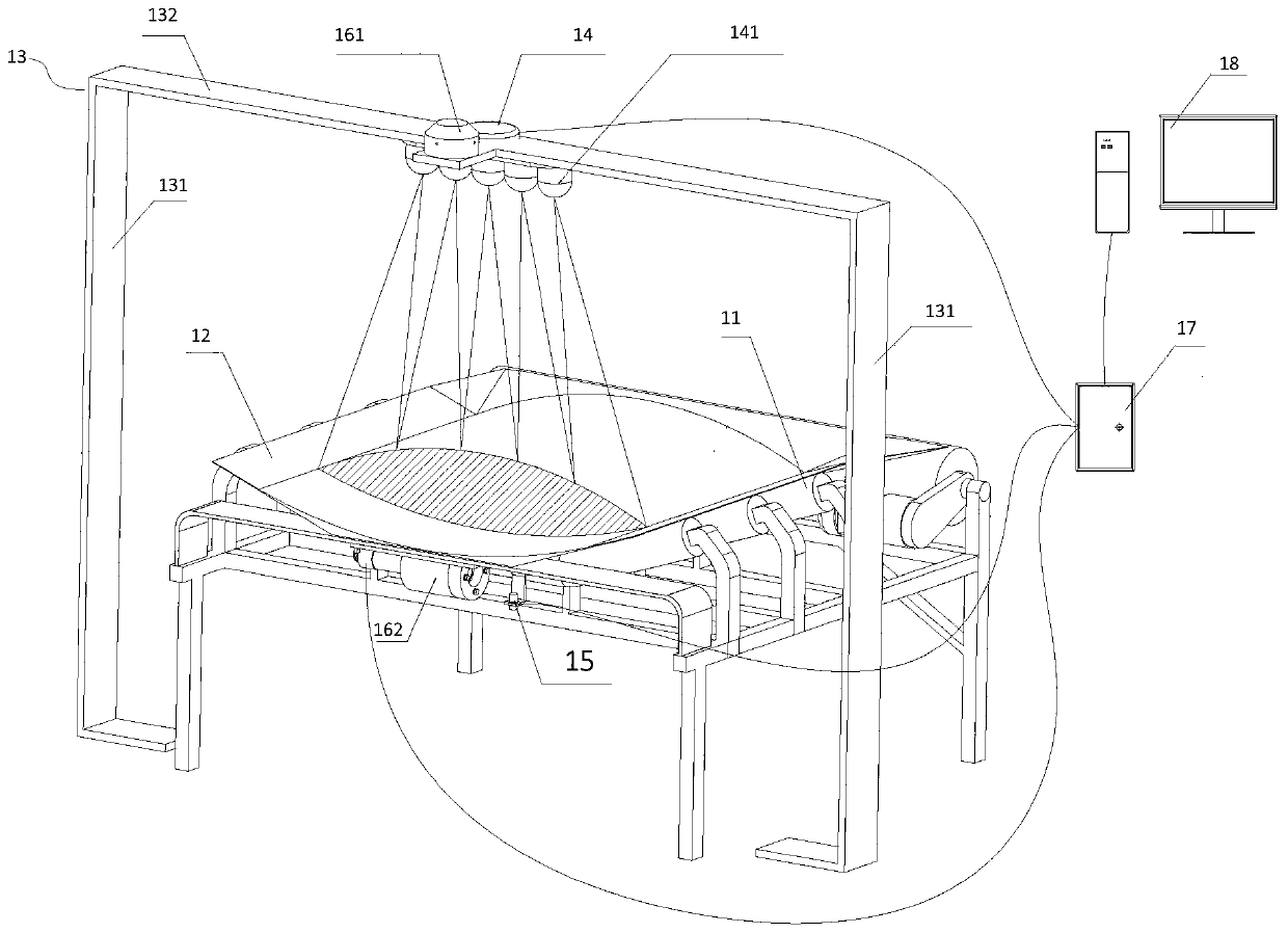
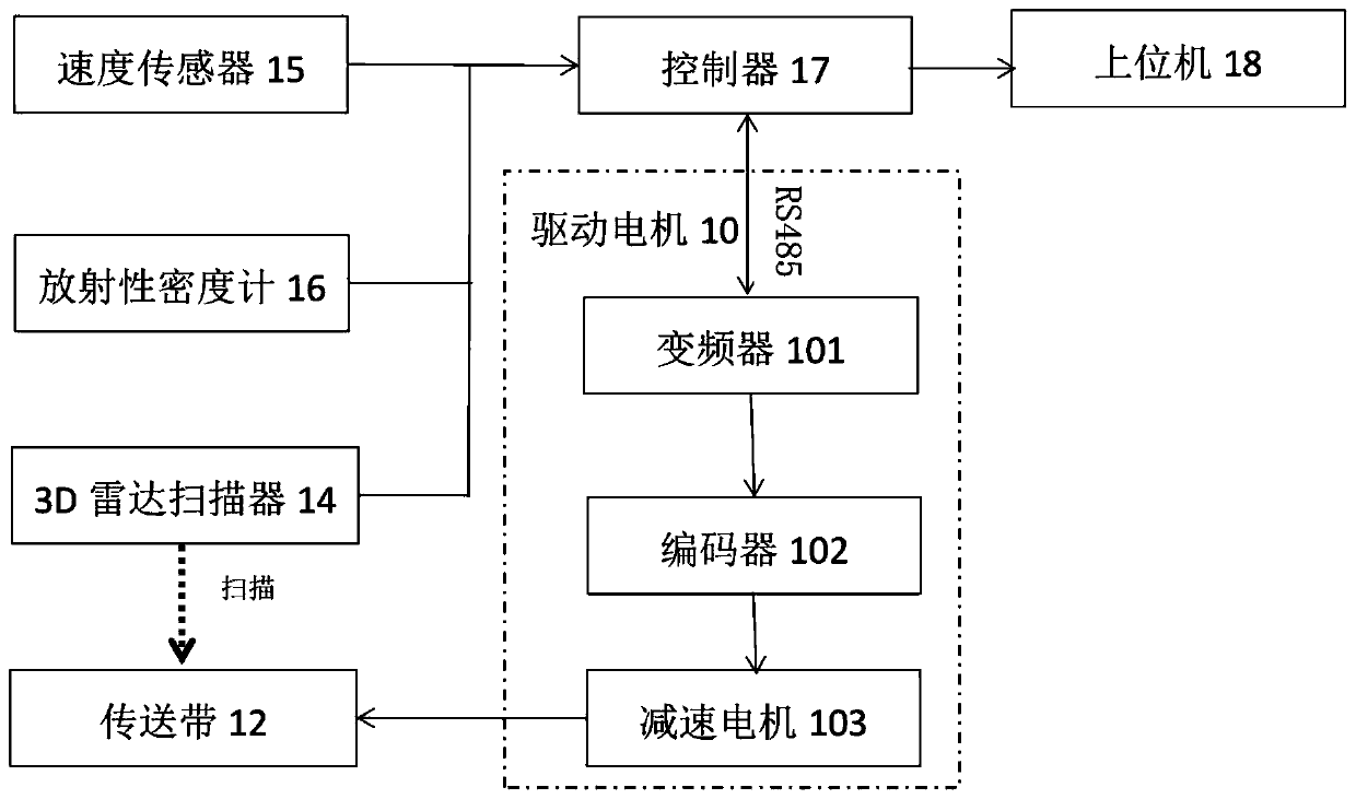
[0046] See attached figure 1 with figure 2 , figure 1 with figure 2 The main structure of a belt material flow control system is exemplarily shown. As shown in the figure, the belt material flow control system provided by the present invention may include: a driving motor 10, an idler roller 11, a conveyor belt 12, a fixed bracket 13, and a 3D radar Scanner 14, speed sensor 15, radioactive density meter 16, controller 17 and host computer 18, drive motor 10 is used to drive conveyor belt 122 to rotate, conveyor belt 12 is arranged on idler 11, 3D radar scanner 14 is fixed on fixed support 13 and above the conveyor belt 12; the 3D radar scanner 14, the speed sensor 15, the radioactive density meter 16, and the drive motor 10 are connec...


PUM


Abstract

A belt material flow control system comprises a driving motor, carrier rollers, a conveying belt, a fixing bracket, a 3D radar scanner, a speed sensor, a radioactive density meter, a controller and anupper computer; the driving motor is used for driving the conveying belt to rotate; the conveying belt is arranged on the carrier rollers; the 3D radar scanner is fixed to the fixing bracket and located above the conveying belt; the 3D radar scanner, the speed sensor, the radioactive density meter and the driving motor are in communication connection with the controller, and the controller is incommunication connection with the upper computer; the 3D radar scanner is used for measuring 3D contour line information of a material; the speed sensor is used for measuring speed information of theconveying belt; the radioactive density meter is used for measuring density information of the material; and the controller is used for selectively controlling the rotation speed of the driving motoraccording to the material mass or material volume. Thus, data of the material on the conveying belt can be precisely measured, the speed of the conveying belt is controlled, thus, the material flow onthe belt can be the best, energy saving and consumption reducing are achieved, and the service life of a belt conveyor is prolonged.

Description

technical field [0001] The invention relates to the field of bulk material conveying control, in particular to a belt material control system. Background technique [0002] Bulk material conveying belts are more and more widely used in the industrial field, and the requirements for the control of material flow on the belt are getting higher and higher. For deviation, material spilling, belt tearing, material blocking, and material increase or decrease, these often occur At present, manual inspection or manual observation in the main control room is required through video technology. However, due to the large amount of dust interference during the transportation of bulk materials, these technologies cannot achieve automatic control. As the labor cost of modern factories is getting higher and higher, and the degree of automation and informatization is getting higher and higher, so the data collection of the material surface of the belt is becoming more and more accurate. If t...

Claims


Application Information

Patent Timeline
IPC IPC(8): B65G43/08
CPCB65G43/08
Inventor 孙丰凯杨晟晔
Owner BEIJING JINDE CHUANGYE CONTROL TECH
Why Eureka
Try Eureka