
Preparation device and method of ice for complete machine ice swallowing test of aero-engine

A technology for aero-engines and preparation devices, which is applied in ice making, application, and ice manufacturing, etc. It can solve the problems of difficult ice demoulding, long ice making time, and poor ice durability, and achieves unbreakable, reduced volume loss, and easy demoulding simple effect

Active Publication Date: 2020-06-16
AECC SHENYANG ENGINE RES INST
View PDF9 Cites 5 Cited by
  • Summary
  • Abstract
  • Description
  • Claims
  • Application Information

AI Technical Summary

Problems solved by technology

[0003] The existing ice-making technology generally uses refrigerators to make ice, that is, ice trays or iron trays are filled with water and placed in the freezing layer of the refrigerator to make ice. This ice-making method has the following disadvantages: ice trays are used to make ice, plastic or other non- It is difficult to separate the ice tray made of elastic material from the ice, and even the ice tray may be damaged. If the ice tray produces smaller ice, the durability of the ice is poor; the ice tray is made of iron, and the tray and Ice separation is difficult, the ice making time is long, and the resulting ice is difficult to demould
In terms of technology, the national military standard clearly states that the density of ice used for the ice swallowing test of the whole machine is 0.80g / cm 3 ~0.90g / cm 3 However, the existing ice-making schemes are generally carried out under normal pressure, and there is almost no requirement for the density of ice. The density of ice under normal pressure is 0.917g / cm 3 , which cannot meet the density requirements of the ice used in the ice swallowing test of the whole machine in the national military standard

Method used


Image

  • Preparation device and method of ice for complete machine ice swallowing test of aero-engine
  • Preparation device and method of ice for complete machine ice swallowing test of aero-engine
  • Preparation device and method of ice for complete machine ice swallowing test of aero-engine

Examples


Embodiment Construction

[0042] In order to make the purpose, technical solution and advantages of the application more clear, the technical solution in the embodiment of the application will be described in more detail below in conjunction with the drawings in the embodiment of the application. In the drawings, the same or similar reference numerals denote the same or similar elements or elements having the same or similar functions throughout. The described embodiments are some, but not all, embodiments of the application. The embodiments described below by referring to the figures are exemplary, and are intended to explain the present application, and should not be construed as limiting the present application. Based on the embodiments in this application, all other embodiments obtained by persons of ordinary skill in the art without creative efforts fall within the protection scope of this application. Embodiments of the present application will be described in detail below in conjunction with th...


PUM


Abstract

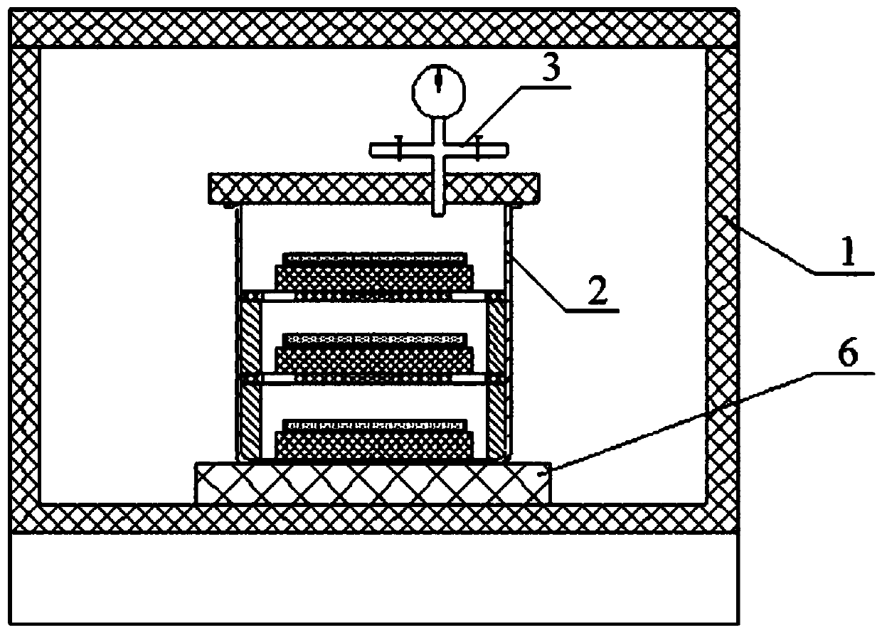
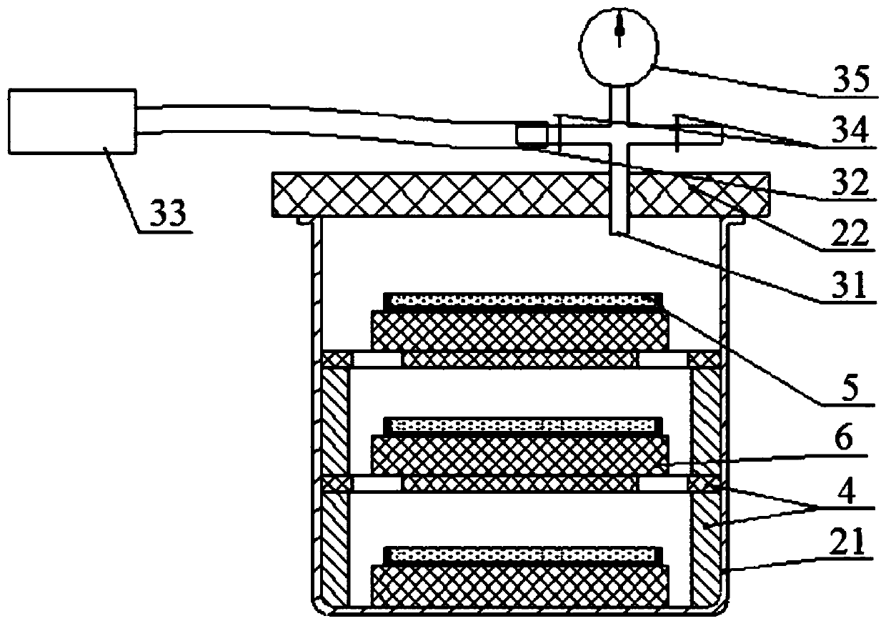
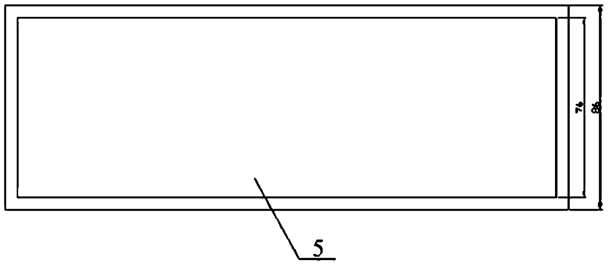
The invention belongs to the technical field of aero-engine tests, and particularly relates to a preparation device and method of ice for a complete machine ice swallowing test of an aero-engine. Thedevice comprises a temperature control freezer (1), a vacuum barrel (2) and a silica gel mold (5), wherein the vacuum barrel (2) is arranged in the temperature control freezer (1), the vacuum barrel (2) comprises a vacuum barrel body (21) and a vacuum barrel cover (22), a pressure control assembly (3) is installed on the vacuum barrel cover (22), and a partition plate assembly (4) is arranged in the vacuum barrel (2); and the silica gel mold (5) is arranged on the partition plate assembly (4). According to the preparation device of the ice for the complete machine ice swallowing test of the aero-engine, low-density ice can be prepared, the density requirement of ice for the complete machine ice swallowing test in the national military standard is met, the silica gel mold is easy to demoldand not prone to being broken, and the volume loss of the ice is reduced.

Description

technical field [0001] The application belongs to the technical field of aero-engine testing, and in particular relates to a device and method for preparing ice flakes for an aero-engine complete machine ice swallowing test. Background technique [0002] Modern civil aviation aircraft have a wide range. Under complex meteorological conditions, the aircraft may encounter hail during flight, and the ice accumulated in the engine inlet may suddenly fall off and be inhaled by the engine. Therefore, the engine must undergo an ice swallowing test. The purpose is to evaluate the performance of the engine and the ability to resist ice impact when the engine encounters the above two situations, and to verify the impact and consequences of the engine due to the impact of hail or ice flakes. The ice swallowing test is one of the test items stipulated in the military specifications of aeroengines and civil aviation airworthiness requirements. The engine ice swallowing test generally has...

Claims


Application Information

Patent Timeline
Patent Type & Authority Applications(China)
IPC IPC(8): F25C1/04F25C1/243
CPCF25C1/04F25C1/243F25C2400/12F25C2400/14
Inventor 安中彦魏峰杨雷田昊张昕东
Owner AECC SHENYANG ENGINE RES INST
Learn More