Method for improving MIMO radar angle resolution and target positioning method

An angular resolution and radar technology, applied in the radio frequency field, can solve problems such as the limited antenna aperture improvement capability, and achieve the effects of improving competitiveness, reducing complexity, and expanding the field of view

Active Publication Date: 2020-06-16
ZHEJIANG LAB
View PDF6 Cites 6 Cited by
  • Summary
  • Abstract
  • Description
  • Claims
  • Application Information

AI Technical Summary

Problems solved by technology

Traditional real-aperture radar increases the antenna aperture by increasing the number of receiving antennas. However, due to the limitation of cost, hardware resources and manufacturing process, the ability to increase the antenna aperture is limited.

Method used


Image

  • Method for improving MIMO radar angle resolution and target positioning method
  • Method for improving MIMO radar angle resolution and target positioning method
  • Method for improving MIMO radar angle resolution and target positioning method

Examples


Embodiment 1

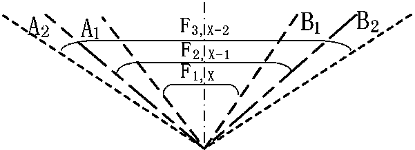
[0055] 2 transmitting 4 receiving radar chips, the distance between adjacent receiving antennas is 0.5λ 0 , the distance between adjacent transmitting antennas is 2λ 0 , which is equivalent to 8 virtual receiving antennas through the MIMO array, and the distance between the virtual receiving antennas is d v 0.5λ 0 . Use the traditional method to get the best angular resolution θ at θ=0° res =λ 0 / (N·d V ·cosθ)=λ 0 / (8×0.5λ 0 )=0.25 rad, or 14.33°. Adopt method of the present invention, minimum FOV=2arcsin (λ 0 / 2d 1,8 )=0.2506 rad, or 14.36°. The FOV angle difference between the 1st and 8th virtual receiving antennas and the 2nd and 7th virtual receiving antennas is Δθ 1,8 =arcsin(λ 0 / 2d 2,7 )-arcsin(λ 0 / 2d 1,8 )=0.018 rad, that is, 1.03°, the angular resolution is increased by 14.33 / 1.03=13.9 times.

Embodiment 2

[0057] 3 transmitting 4 receiving radar chips, the distance between adjacent receiving antennas is 0.5λ 0 , the distance between adjacent transmitting antennas is 2λ 0 , which is equivalent to 12 virtual receiving antennas through the MIMO array, and the distance between the virtual receiving antennas is d v 0.5λ 0 . Use the traditional method to get the best angular resolution θ at θ=0° res =λ 0 / (N·d V ·cosθ)=λ 0 / (12×0.5λ 0 )=0.167 rad, or 9.55°. Adopt method of the present invention, minimum FOV=2arcsin (λ 0 / 2d 1,12 )=0.1668 rad, or 9.56°. The FOV angle difference between the 1st and 12th virtual receiving antennas and the 2nd and 11th virtual receiving antennas is Δθ 1,12 =arcsin(λ 0 / 2d 2,11 )-arcsin(λ 0 / 2d 1,12 )=0.0076 rad, that is, 0.43°, and the angle resolution improvement factor is 9.55 / 0.43=22.2 times.

Embodiment 3

[0059] 4 transmitting 4 receiving radar chips, the distance between adjacent receiving antennas is 0.5λ 0 , the distance between adjacent transmitting antennas is 2λ 0 , which is equivalent to 16 virtual receiving antennas through the MIMO array, and the distance between the virtual receiving antennas is d v 0.5λ 0 . Use the traditional method to get the best angular resolution θ at θ=0° res =λ 0 / (N·d V ·cosθ)=λ 0 / (16×0.5λ 0 )=0.125 rad, or 7.12°. Adopt method of the present invention, minimum FOV=2arcsin (λ 0 / 2d 1,16 )=0.1251 rad, or 7.16°. The FOV angle difference between the 1st and 16th virtual receiving antennas and the 2nd and 15th virtual receiving antennas is Δθ 1,16 =arcsin(λ 0 / 2d 2,15 )-arcsin(λ 0 / 2d 1,16 )=8.95×10 -3 rad, which is 0.51°, the angular resolution is increased by 7.12 / 0.51=13.9 times.


PUM


Abstract

The invention discloses a method for improving MIMO radar angle resolution and a target positioning method. According to the method, an MIMO radar forms an equivalent virtual receiving antenna array by reasonably arranging a transmitting antenna and a receiving antenna, phase shift is carried out on the receiving antenna and a transmitting antenna feed circuit by utilizing the phase difference ofa virtual receiving channel, and the position of a target is accurately judged in combination with the change of a view field range. According to the invention, on the basis of the MIMO radar equivalent virtual antenna array, the angular resolution of the radar is further improved; therefore, the number of the receiving antennas and the number of the transmitting antennas are reduced, the technical barrier that the radar angle resolution is improved by means of cascading complex hardware circuits is broken through, and the problems that high-angle-resolution radar hardware is complex in structure, large in size, high in power consumption, high in cost and the like are fundamentally solved.

Description

technical field [0001] The invention relates to the field of radio frequency technologies such as electromagnetic wave signal transmission, reception, phase shifting, and beam scanning, and in particular to a method for improving the angular resolution of a MIMO radar and a target positioning method. Background technique [0002] Radar is the abbreviation of radio detection and ranging (radar). Compared with traditional radar, MIMO (Multiple-Input Multiple-Output) radar can improve the energy utilization rate of the system and improve the angle measurement. Accuracy, improved clutter suppression ability and low interception ability, so it has gradually become an innovative and promising frontier research field in the radar industry. MIMO radar is widely used in smart cities, such as advanced driver assistance systems (ADAS), commercial building automation and intelligent monitoring, intelligent traffic monitoring, factory machine and human cooperation safety protection, smar...

Claims


Application Information

Patent Timeline
Patent Type & Authority Applications(China)
IPC IPC(8): G01S13/02G01S7/42
CPCG01S7/42G01S13/02G01S2013/0236
Inventor 邓庆文杨李杰曾玉明郭清水徐志伟
Owner ZHEJIANG LAB
Why Eureka
Try Eureka