Bidirectional switch floating drive circuit and multi-way switch drive circuit thereof

A bidirectional switch and drive circuit technology, applied in the direction of electrical components, output power conversion devices, etc., can solve problems such as high cost, limited application range, complicated circuit, etc., and achieve the effect of low cost and simple circuit design

Inactive Publication Date: 2020-06-16
SHENZHEN BOMIN ELECTRONICS +1
View PDF7 Cites 2 Cited by
  • Summary
  • Abstract
  • Description
  • Claims
  • Application Information

AI Technical Summary

Problems solved by technology

[0003] When the high-level floating switch device is working, it must use floating driving technology to turn it on or off. Generally, chips containing floating driving technology are often expensive, and a type of floating driving chip only corresponds to a type of circuit, which cannot be achieved. The general purpose of the floating driver chip cannot be applied to some specific situations, such as high voltage and ultra-high frequency applications. The floating driver chip needs to be equipped with peripheral circuits, thereby increasing the number of devices, causing the driving signal to be easily interfered, and the reliability is not high.
[0004] The traditional isolation driving method is: each high-level floating switch tube needs one PWM waveform to control it. If the number of switch tubes is large, the general MCU will not be able to meet the demand for the number of high-level floating switch tubes in the circuit. The control chip will lead to more complex circuits, increase the cost of the entire system, and limit its application range
[0005] In the DC circuit breaker, the switching tube needs to be turned on or off for a long time, but the commonly used traditional drive circuit (such as the attached figure 1 As shown) it is difficult to realize the long-time conduction of the switch tube, and the circuit design is more difficult; in order to realize the long-time conduction of the switch tube, the optocoupler drive circuit is commonly used in the DC circuit breaker (as shown in the attached figure 2 As shown) to realize the long-term driving of the switch tube, the secondary side of the optocoupler driving circuit needs to use additional power supply, and the corresponding power supply circuit design is more complicated and the cost is higher

Method used


Image

  • Bidirectional switch floating drive circuit and multi-way switch drive circuit thereof
  • Bidirectional switch floating drive circuit and multi-way switch drive circuit thereof
  • Bidirectional switch floating drive circuit and multi-way switch drive circuit thereof

Examples


Embodiment Construction

[0038] The present invention will be further described below in conjunction with the accompanying drawings and embodiments.

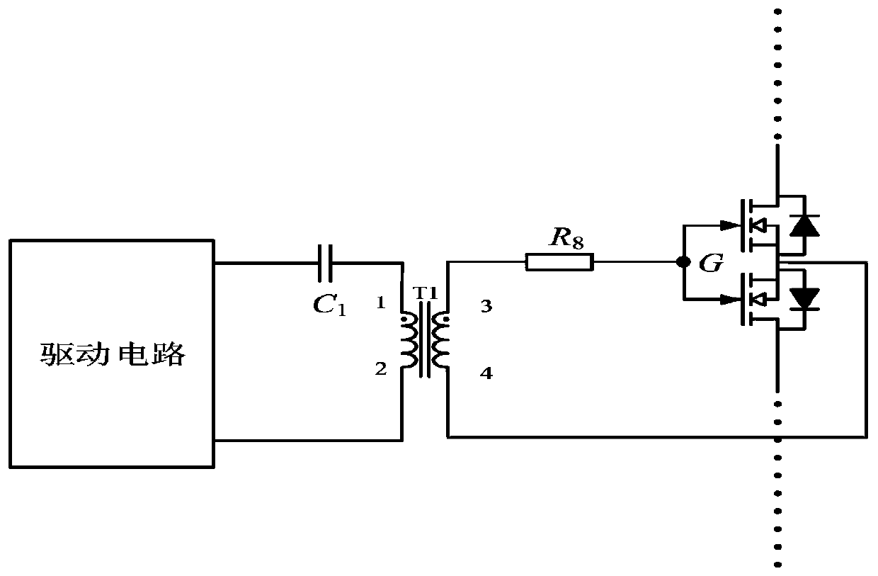
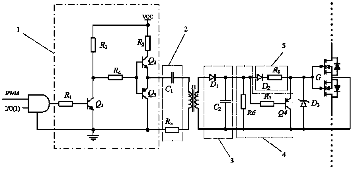
[0039] as attached image 3 As shown, a bidirectional switch floating drive circuit includes a primary side drive generation circuit, a primary side drive amplifier circuit 1, an isolation drive transformer T1, a secondary side half-wave rectifier circuit 3 and a floating drive circuit electrically connected in sequence;

[0040] The primary-side drive generating circuit includes an AND gate and two AND gate input signals, wherein the input signal of one AND gate is PWM wave, and the input signal of the other AND gate is an I / O signal capable of generating high and low levels, among which, The PWM wave and I / O signals are all generated by the single-chip microcomputer, and the output terminal of the AND gate is connected to the input terminal of the primary side drive amplifier circuit 1, and the primary side drive amplifier circuit 1 is used to amplify...


PUM


Abstract

The invention discloses a bidirectional switch floating drive circuit and a multi-way switch drive circuit thereof. The bidirectional switch floating drive circuit comprises a primary side drive generation circuit, a primary side drive amplification circuit, an isolation drive transformer T1, a secondary side half-wave rectification circuit and a floating drive circuit. The primary side drive generation circuit comprises an AND gate and two paths of input signals, wherein one path is a PWM wave, and the other path is an I/O signal; the isolation drive transformer T1 comprises a primary windingN1 and a secondary winding N2; the secondary side half-wave rectification circuit comprises a rectifier diode D1 and a secondary side filter capacitor C2; and the floating drive circuit comprises a bidirectional switch tube G, wherein the bidirectional switch tube G comprises two N-type MOS transistors, grid electrodes and source electrodes of the two MOS transistors are respectively connected together. According to the invention, long-time conduction or closing of the bidirectional switching tube can be conveniently realized only by controlling the level state of the I/O signal.

Description

technical field [0001] The invention relates to the technical field of switch circuits, in particular to a bidirectional switch floating drive circuit and a multi-way switch drive circuit thereof. Background technique [0002] Due to the high efficiency of switching power supplies, most of the power supplies currently on the market are switching power supplies. With the continuous development of switching power supply technology, many topologies with excellent performance and unique structure have emerged. The rapid development of topologies has promoted the demand for isolated drives. As a result, isolation drives have a high usage rate in floating drive topologies, and isolation drives also ensure the stability and reliability of switching power supplies. [0003] When the high-level floating switch device is working, it must use floating driving technology to turn it on or off. Generally, chips containing floating driving technology are often expensive, and a type of flo...

Claims


Application Information

Patent Timeline
Patent Type & Authority Applications(China)
IPC IPC(8): H02M1/088
CPCH02M1/088
Inventor 王强章治国曾俊徐俊子徐缓
Owner SHENZHEN BOMIN ELECTRONICS
Why Eureka
Try Eureka