Optical camera lens

A camera and lens technology, applied in the field of cameras, can solve the problems of poor heat conduction effect, out-of-focus lens, poor heat conduction effect between the lens cover and the lens holder, etc., and achieves the effect of solving lens fogging and low cost.

Pending Publication Date: 2020-06-16
WUJIANG XUWEI ELECTRONICS TECH CO LTD +1
View PDF0 Cites 3 Cited by
  • Summary
  • Abstract
  • Description
  • Claims
  • Application Information

AI Technical Summary

Problems solved by technology

[0002] As an imaging tool, the application scope of the camera continues to expand, and it has been widely used in mobile terminals, automobiles, drones, video security, AR and other fields. The existing cameras have the following problems: (1) First, the problem of overheating of the camera, The existing plastic material lens cover and lens mount have poor thermal conductivity. High temperature can easily cause the sensor converter to overheat, affecting image quality. High temperature can also cause the focal length of the lens to change and lose focus. The industry is currently unable to solve this problem.
[0003] (2) The installation method of the lens on the market: there are C type and CS type, the thread of both is 1 inch and 32 teeth, the difference is that the distance between the lens and the CCD target surface is different. It can focus normally, but the poor matching rate of the screw teeth is too high, the adjusted focal length is easy to change if the teeth are loose, and it is difficult to adjust the teeth if it is tight
[0004] (3) The heat conduction effect of the existing plastic lens and lens holder is not good, and high temperature may easily cause the CMOS of the sensor to overheat, affecting the image quality
At the same time, the inside of the camera is overheated, and the temperature of the external environment is low. The natural physical phenomenon of lens fogging will occur, which will affect the imaging effect. High temperature will also cause the focal length of the lens to change and lose focus. The industry is currently unable to solve this problem.

Method used


Image

  • Optical camera lens
  • Optical camera lens
  • Optical camera lens

Examples


Embodiment 1

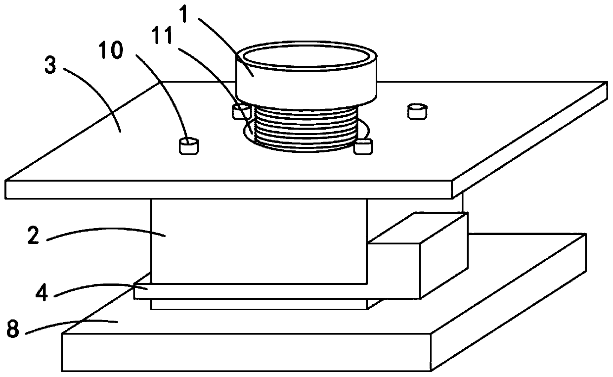
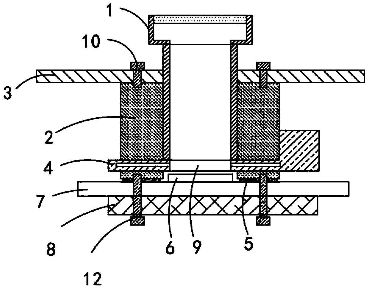
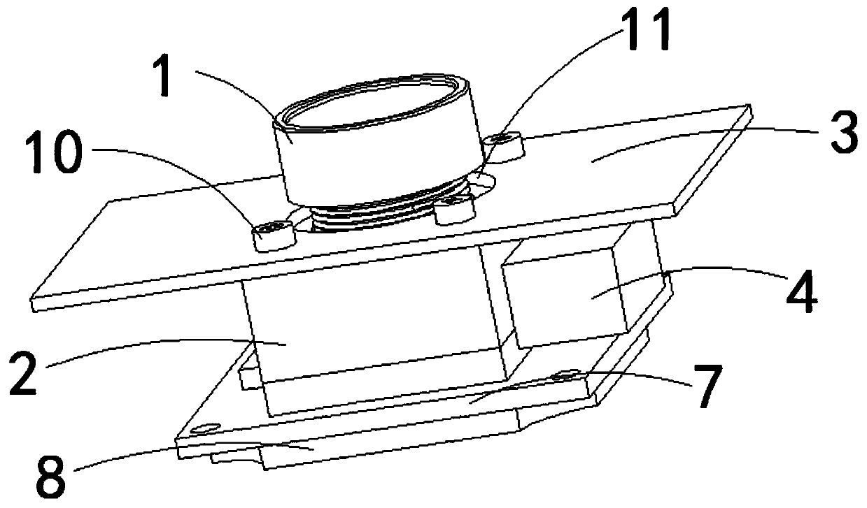
[0024] see Figure 1-4 , an optical camera lens, including a lens 1 and a lens holder 2, the thread between the lens 1 and the lens holder 2 is added with thermally conductive silicone gel, and the thermally conductive silicone gel is based on two-component A and B-component silicone oil. Add 300%-1000% of thermally conductive fillers to components A and B separately by mass percentage. Thermally conductive fillers include alumina, magnesia, and boron nitride. Semi-fluid thermal conductivity: 1–5W / m*K, temperature resistance -40-200°C, fireproof 94V0 heat conduction paste material, before the lens and lens mount lock screw are assembled, apply a film on the lens thread 1:1 and mix AB group The heat-conducting silicone gel can be assembled after the heat-conducting silicone gel is divided. The heat-conducting silicone gel can play the role of caulking. In addition, the heat-conducting silicone gel is self-adhesive. Internal thread, the surface of lens 1 is provided with extern...

Embodiment 2

[0026] see Figure 1-4 , an optical camera lens, including a lens 1 and a lens holder 2, the thread between the lens 1 and the lens holder 2 is added with thermally conductive silicone gel, and the thermally conductive silicone gel is based on two-component A and B-component silicone oil. Add 300%-1000% of thermally conductive fillers to components A and B separately by mass percentage. Thermally conductive fillers include alumina, magnesia, and boron nitride. Semi-fluid thermal conductivity: 1–5W / m*K, temperature resistance -40-200°C, fireproof 94V0 heat conduction paste material, before the lens and lens mount lock screw are assembled, apply a film on the lens thread 1:1 and mix AB group The heat-conducting silicone gel can be assembled after the heat-conducting silicone gel is divided. The heat-conducting silicone gel can play the role of caulking. In addition, the heat-conducting silicone gel is self-adhesive. Internal thread, the surface of lens 1 is provided with extern...

Embodiment 3

[0028] Based on Examples 1 and 2, such as figure 2 , a support plate 3 is provided above the lens holder 2, and a circular opening 11 that penetrates up and down is provided in the middle of the support plate 3. The upper end of the lens 1 is provided with a circular head 11 and extends to the top. A plurality of second fixing bolts 10 are provided, and the support plate 3 and the lens holder 2 are threadedly connected by the second fixing bolts 10. The support plate 3 is made of copper or aluminum material, and the setting of the support plate 3 can improve the heat conduction effect.

[0029] Working principle: when in use, the scene is projected onto the surface of the image sensor 6 through the optical image generated by the lens 1, and then converted into an electrical signal through the pcb circuit board 7, and then converted into a digital image signal after A / D conversion, and then sent to the digital processing chip After processing, the lens holder 2 is changed from...


PUM

PropertyMeasurementUnit
thermal conductivityaaaaaaaaaa

Abstract

The invention relates to the technical field of cameras. The invention further discloses an optical camera lens. The optical camera lens comprises a lens and a lens mount, the lens mount is provided with a through hole which is through up and down. An internal thread is arranged on the inner wall of the through hole; and the surface of the lens is provided with external threads. The lens is in threaded connection in the through hole; a groove is formed in one side of the lens mount; an opening penetrating up and down is formed in a position, corresponding to the lens, of the optical filter; and the bottom surface of the lens mount is provided with a pcb circuit board. According to the optical camera lens, the problem that the temperature of the camera is too high and the problem that the lens is fogged are solved through material replacement test argumentation, and a finished product is more durable than a PC material with the heat conductivity coefficient of 0.2 used in the existing market and is much lower than a metal material in price.

Description

technical field [0001] The invention relates to the technical field of cameras, in particular to an optical camera lens. Background technique [0002] As an imaging tool, the application scope of the camera continues to expand, and it has been widely used in mobile terminals, automobiles, drones, video security, AR and other fields. The existing cameras have the following problems: (1) First, the problem of overheating of the camera, Existing plastic lens caps and lens mounts do not perform well in heat conduction. High temperatures can easily lead to overheating of the sensor converter, affecting image quality. High temperatures can also cause changes in the focal length of the lens and cause it to lose focus. The industry is currently unable to solve this problem. [0003] (2) The installation method of the lens on the market: there are two types: C type and CS type. It can focus normally, but the poor matching rate of the screw teeth is too high, the focal length adjuste...

Claims


Application Information

Patent Timeline
Patent Type & Authority Applications(China)
IPC IPC(8): H04N5/225
CPCH04N23/54H04N23/50H04N23/55
Inventor 孙清稳
Owner WUJIANG XUWEI ELECTRONICS TECH CO LTD
Why Eureka
Try Eureka