Automobile man-machine co-driving mode brake control system and control method

A braking control, human-machine technology, applied in the direction of control devices, etc., can solve problems such as stable braking, vehicle deceleration, and inability of the vehicle to decelerate.

Active Publication Date: 2020-06-19
DONGFENG LIUZHOU MOTOR
View PDF33 Cites 3 Cited by
  • Summary
  • Abstract
  • Description
  • Claims
  • Application Information

AI Technical Summary

Problems solved by technology

[0003] The present invention provides a brake control system and control method in the man-machine co-driving mode of an automobile. When the braking force output is less than the power output, the vehicle cannot decelerate. When the requested braking force output is greater than the power output, the vehicle will suddenly decelerate. The vehicle cannot brake stably according to the requested deceleration

Method used


Image

  • Automobile man-machine co-driving mode brake control system and control method

Examples


Embodiment Construction

[0017] The present invention will be described in further detail below in conjunction with accompanying drawing embodiment:

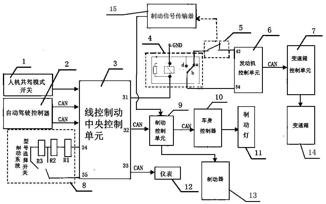
[0018] figure 1 The brake control system of the car man-machine co-driving mode shown includes a brake-by-wire central control unit 3 and a pedal travel switch 5, and the pedal travel switch 5 is connected to the brake 13 through a brake signal transmitter 15 and a brake control unit 9 The brake-by-wire central control unit 3 has a signal sampling terminal 34, a loop ground terminal 35, a relay power supply control terminal 31, an external brake request output terminal 32, a fault information output terminal 33, and multiple signal input terminals. One signal input end of the unit 3 is connected to the signal output end of the man-machine co-driving mode switch 1, and the other two signal input ends of the brake-by-wire central control unit 3 are respectively connected to the two signals of the automatic driving controller 2 through the CAN bus. The ou...


PUM


Abstract

The invention discloses an automobile man-machine co-driving mode brake control system and a control method and belongs to the technical field of automobile manufacturing. The system comprises a brake-by-wire central control unit and a pedal travel switch connected with a brake through a brake control unit, wherein an input end of the brake-by-wire central control unit is correspondingly connectedwith output ends of the man-machine co-driving mode switch and an automatic driving controller, a relay and a pedal travel switch are sequentially connected between a relay power supply control end of the brake-by-wire central control unit and a loop ground end of an engine control unit, a switching signal sampling end of the engine control unit is connected with a common contact end of the relay, and the engine control unit is connected with a gearbox through a gearbox control unit. The system is advantaged in that a problem that the vehicle cannot be stably braked according to the requesteddeceleration in the automatic driving mode of the existing vehicle with both manual driving and automatic driving can be solved.

Description

technical field [0001] The invention relates to the technical field of automobile manufacturing, in particular to a braking control system and a control method in a human-machine co-driving mode of an automobile. Background technique [0002] The existing automobile brake control system includes a pedal travel switch connected to the brake through a brake control unit, and the signal output end of the pedal travel switch is connected to the gearbox through the engine control unit and the gearbox control unit in turn. When the driver depresses the brake pedal, the pedal travel switch is disconnected, and the brake signal generated by it is input to the brake through the brake control unit to brake the whole vehicle, and is also input to the gearbox control unit through the engine control unit, so as to Determine whether the vehicle speed and rotation speed match, and then control the gearbox to reduce or cut off the power output, so as to prevent the fixed-point braking from ...

Claims


Application Information

Patent Timeline
Patent Type & Authority Applications(China)
IPC IPC(8): B60W10/06B60W10/10B60W10/18B60W50/08B60W50/14B60W60/00
CPCB60W10/06B60W10/10B60W10/18B60W50/082B60W50/14B60W2050/146
Inventor 覃熊艳姚柳成梁丽丽李育方王善超韦红庆李炳志
Owner DONGFENG LIUZHOU MOTOR
Why Eureka
Try Eureka