Anti-pilling flannel production process and production device

A ball flannel, technology for producing devices, applied in textile and papermaking, fabric surface trimming, fabric elongation, etc.

Inactive Publication Date: 2020-06-19
王晓虎
View PDF1 Cites 1 Cited by
  • Summary
  • Abstract
  • Description
  • Claims
  • Application Information

AI Technical Summary

Problems solved by technology

However, this device cannot stretch the flannel that has just been dried to prevent wrinkles inside the fiber

Method used


Image

  • Anti-pilling flannel production process and production device
  • Anti-pilling flannel production process and production device
  • Anti-pilling flannel production process and production device

Examples


specific Embodiment approach 1

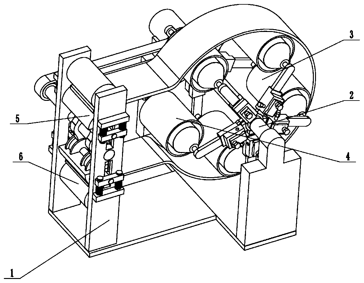
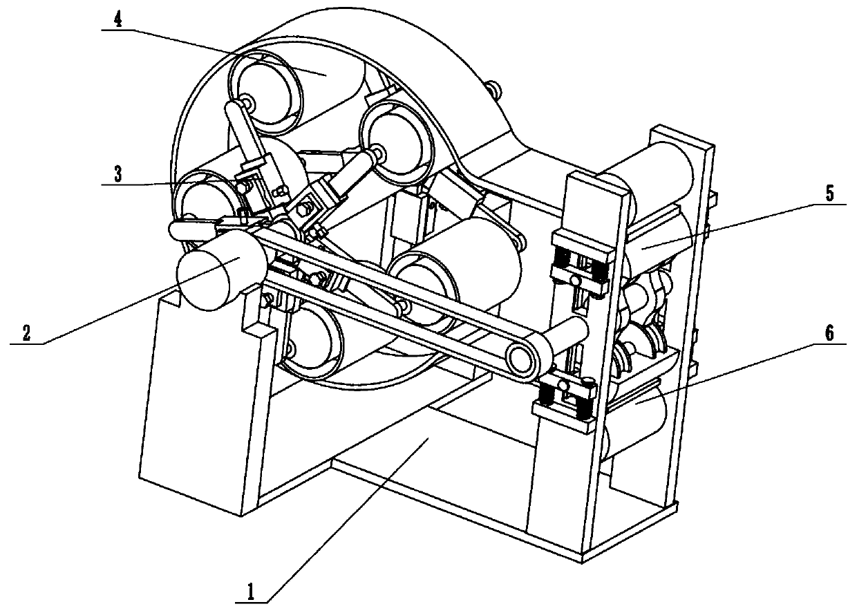
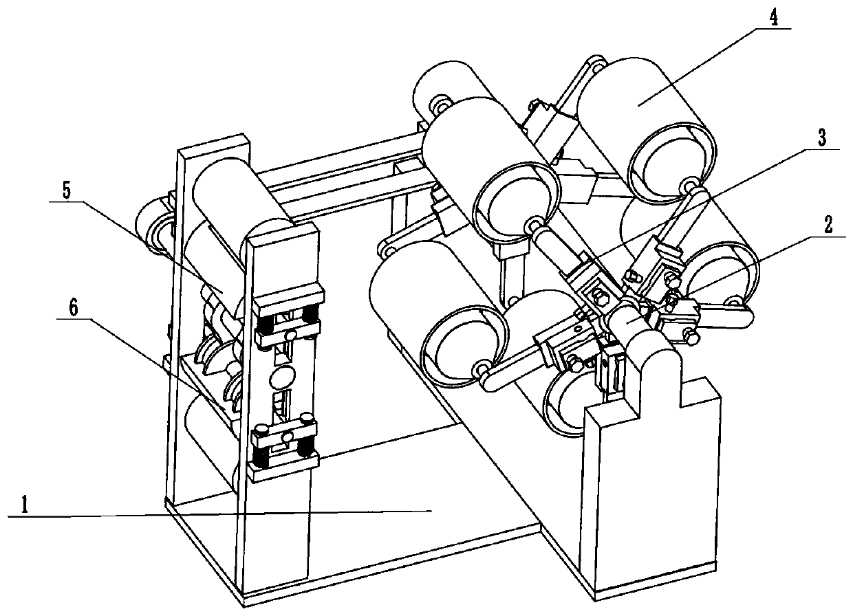
[0036] Such as Figure 1 to Figure 14 As shown, an anti-pilling flannel and production device includes a processing frame 1, a combined drive 2, two stretching regulators 3, a plurality of stretching rotating cylinders 4, an upper intermittent fixing seat 5 and a lower intermittent fixing seat 6, the combined driver 2 is rotatably connected in the processing frame 1, the two stretch regulators 3 are fixedly connected to the combined driver 2, and a plurality of stretch rotating cylinders 4 are evenly fixedly connected to the two stretch regulators. Between the devices 3, the lower end of the upper intermittent fixing seat 5 and the upper end of the lower intermittent fixing seat 6 are all slidably connected to the combined drive 2, and the upper intermittent fixing seat 5 and the lower intermittent fixing seat 6 are all longitudinally slidably connected in the processing frame 1 . The flannel that has just been dried and produced first passes between the processing frame 1 an...

specific Embodiment approach 2

[0038] Such as Figure 1 to Figure 14 As shown, this embodiment will further explain Embodiment 1. The processing frame 1 includes a bottom plate 1-1, a motor fixing seat 1-2, a rotating shaft rotating seat 1-3, two longitudinal fixing plates 1-4, an upper Clamping and fixing stainless steel roller 1-5, lower clamping and fixing stainless steel roller 1-6 and multiple longitudinal chute 1-7, motor fixing seat 1-2 and rotating shaft rotating seat 1-3 are respectively fixedly connected to the base plate 1-1 At the front and rear ends, the two longitudinal fixing plates 1-4 are fixedly connected to the bottom plate 1-1, and the upper clamping and fixing stainless steel roller 1-5 and the lower clamping and fixing stainless steel roller 1-6 are fixedly connected to the two longitudinal fixing plates Between 1-4, the two longitudinal fixing plates 1-4 are provided with a plurality of longitudinal slide grooves 1-7 that run through from front to back. The flannel that has just been...

specific Embodiment approach 3

[0040] Such as Figure 1 to Figure 14 As shown, this embodiment will further illustrate the second embodiment. The combined driver 2 includes a drive motor 2-1, a tension drive shaft 2-2, a main drive pulley 2-3, a slave drive pulley 2-4, an intermittent Fix the driving shaft 2-5 and two driving double-convex driving wheels 2-6, the driving motor 2-1 is fixedly connected on the motor fixing seat 1-2, and one end of the stretching driving shaft 2-2 is connected to the driving motor through a coupling 2-1 of the drive shaft, the other end of the stretching drive shaft 2-2 is connected to the rotating shaft revolving seat 1-3, the main drive pulley 2-3 is fixedly connected to the drive shaft of the drive motor 2-1, the main drive pulley 2-3 is connected to the slave drive pulley 2-4 through a belt drive, and the slave drive pulley 2-4 is fixedly connected to the intermittently fixed drive shaft 2-5, and the intermittently fixed drive shaft 2-5 is rotatably connected to two longit...


PUM


Abstract

The present invention relates to the field of flannel processing, and more particularly relates to an anti-pilling flannel production process and production device. The processing process comprises the following steps of enabling just dried and produced flannel to pass through the position between a processing machine frame and an upper intermittent fixed base, then sleeving the outer walls of a plurality of stretching rotating barrels in sequence, and then passing through the position between the processing machine frame and a lower intermittent fixed base; according to different actual production conditions, synchronously adjusting the specified stretching rotating barrels to extend by the specified length on two stretching adjusters, thereby facilitating stretching of the just dried andproduced flannel; and powering on a combined driver to drive the two stretching adjusters and the multiple stretching rotating barrels to rotate, and extruding the flannel intermittently by the upperintermittent fixed base and the lower intermittent fixed base, thereby facilitating fixation of stretching, and realizing stretching of effective protection of the just dried and produced flannel. The anti-pilling flannel comprises 30% of polyester fibers, 30% of spandex and 40% of pure cotton.

Description

technical field [0001] The flannel processing field of the present invention is more specifically a kind of anti-pilling flannel production technology and production device. Background technique [0002] Patent No. CN201711328020.1 discloses a production process of anti-pilling flannel. It solves technical problems such as complex production process, too many working procedures, and long production cycle. The production process of the anti-pilling flannel, the production process includes the following steps: S1, weaving: the cotton fiber of 60-75 parts by weight and the polyester fiber of 25 / 40 parts by weight are threaded into velvet tissue, and 100D- The FDY of 24F is used as the bottom yarn structure, and the gray cloth is obtained through warping, warp knitting and slitting; S2, pretreatment: desizing and scouring the gray cloth obtained in S1; S3, napping: putting the gray cloth obtained in S2 into combing Combing in the machine, and then use the napping machine to na...

Claims


Application Information

Patent Timeline
IPC IPC(8): D06C3/06
CPCD06C3/06
Inventor 王晓虎
Owner 王晓虎
Why Eureka
Try Eureka