[0020] In order to make the objectives, technical solutions, and advantages of the present invention clearer, the following further describes the present invention in detail with reference to the accompanying drawings and embodiments. It should be understood that the specific embodiments described herein are only used to explain the present invention, but not to limit the present invention.
[0021] The specific implementation of the present invention will be described in detail below in conjunction with specific embodiments.
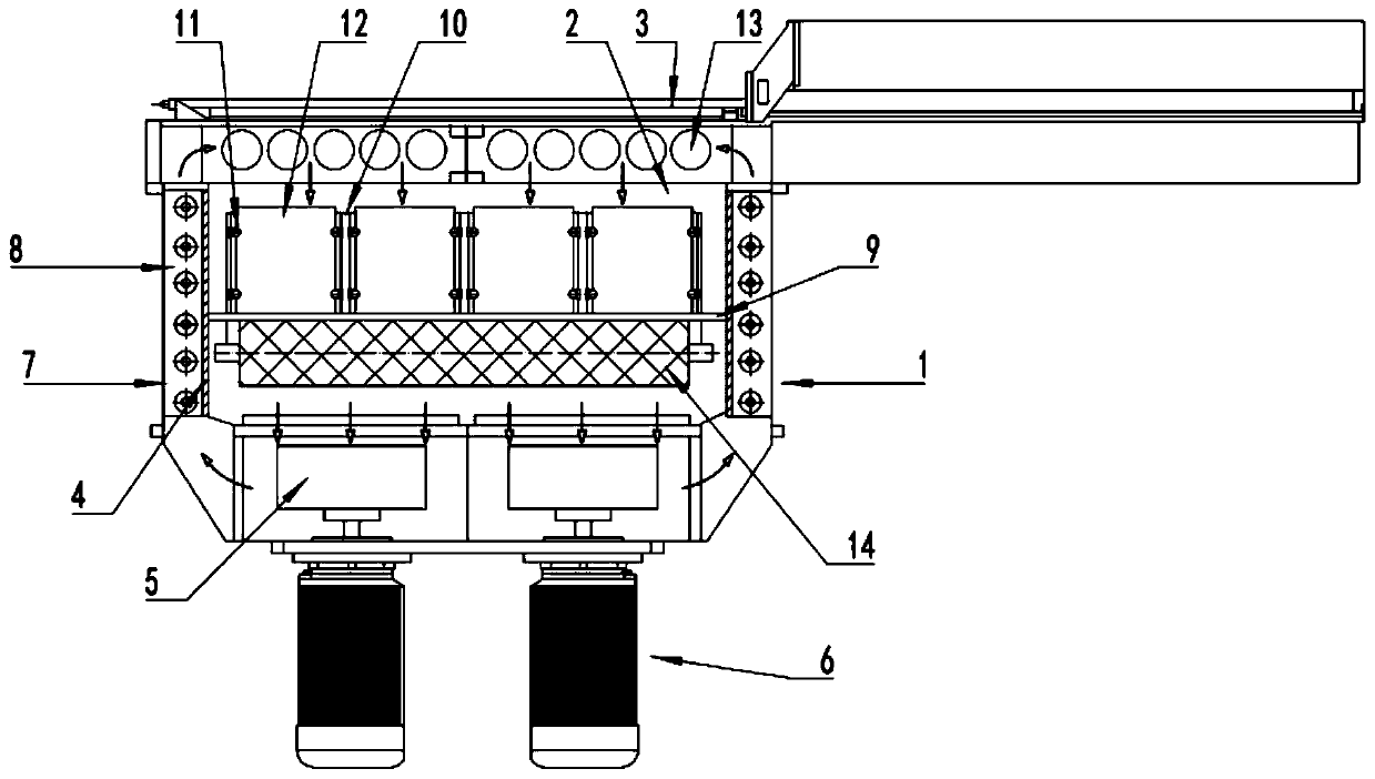
[0022] Such as figure 1 Shown is a structural diagram of a hot air circulation oven with a tank cover provided by an embodiment of the present invention, which includes an oven shell 1, a silicon wafer positioning device 10, and an air circulation device. The oven shell 1 is provided with a partition 4, The oven shell 1 is divided into a drying chamber 2 and an air duct 7, and the oven shell 1 is provided with a tank cover 3 communicating with the air duct 7, a heating device 8 is installed in the air duct 7, and the tank cover 3 is provided with A number of air outlets 13, the air outlet 13 is opposite to the drying chamber 2, that is, the air outlet direction is parallel to the plane of the silicon wafer 12; the silicon wafer positioning device 10 is provided in the drying oven shell 1 The cavity 2 is used for clamping and positioning the silicon wafer 12; the air circulation device is used for circulating hot air between the drying cavity 2 and the air duct 7.
[0023] In actual application, the air enters the tank cover 3 after being heated by the heating device 8. Here, the heating device 8 can be a heating tube, an electric heating wire, etc., which are not specifically limited here. The hot air flows from the tank cover The air outlet 13 provided on 3 enters the drying chamber 2 evenly, and the direction of the hot air is kept parallel to the plane of the silicon wafer 12, which is not easy to cause the silicon wafer 12 to be broken. The hot air will blow the silicon wafer 12 After being dried, the moisture on the surface enters the air duct 7 through the air circulation device and is heated by the heating device 8.
[0024] Such as Figure 1~2 As shown, as a preferred embodiment of the present invention, the silicon wafer positioning device 10 is provided with a universal clamping member 11, and the universal clamping member 11 is used to insert the silicon wafer 12 and adjust the The silicon wafer 12 is described so that the plane where the silicon wafer 12 is located is parallel to the direction of the hot air.
[0025] Since under normal circumstances, the hot air flow is prone to turbulence, resulting in a relative angle between the silicon wafer 12 and the air flow, and the universal clamp 11 is provided to adjust the angle of the silicon wafer 12 according to the air flow angle. Adjust to prevent the silicon wafer 12 from being blown off.
[0026] Such as Figure 1~2 As shown, as another preferred embodiment of the present invention, the universal clamp 11 includes a base 111, a universal ball base 112, and a universal ball 113. The universal ball base 112 is mounted on the base 111 On the silicon wafer positioning device 10, the universal ball 113 is movably matched with the universal ball seat 112, and the universal ball 113 is provided with a positioning groove 114.
[0027] Generally speaking, there are several universal clamps 11 on both sides of a silicon wafer 12, because when the silicon wafer 12 moves, the contact between the silicon wafer 12 and the universal ball 113 is easy to break, so the universal The ball 113 is preferably made of relatively soft and elastic plastic.
[0028] Such as figure 1 As shown, as another preferred embodiment of the present invention, the silicon wafer positioning device 10 is fixed on the placing plate 9, and the placing plate 9 is provided with a number of openings. The placing plate 9 and the oven shell 1 Pull to cooperate.
[0029] The placing plate 9 and the oven shell 1 adopt a pull-and-pull matching method, so that the placing plate 9 and the silicon wafer positioning device 10 can be drawn out from the oven shell 1 more conveniently, and it is convenient to replace the new silicon wafer 12. Of course, the oven shell 1 The corresponding position is provided with an opening or a box door; the opening on the placement plate 9 is to facilitate the hot air to enter the air duct 7 smoothly again.
[0030] Such as figure 1 As shown, as another preferred embodiment of the present invention, a return air filter 14 is connected to the air outlet end of the placing plate 9, and the return air filter 14 stabilizes the wind field and makes it enter the wind circulation device The wind remains stable.
[0031] The return air filter 14 is welded by a mesh plate. The return air filter can effectively avoid the turbulence of the wind field of the return air of the air circulation device, make the wind blown to the silicon wafer 12 more uniform, and can also filter the air.
[0032] Such as figure 1 As shown, as another preferred embodiment of the present invention, the air circulation device includes a fan blade 5 and a motor 6. The fan blade 5 is located at the connection between the air duct 7 and the drying chamber 2, and the fan blade 5 Driven by a motor to rotate.
[0033] The main function of the fan blade 5 is to blow the hot air (return air) in the drying chamber 2 into the air duct 7 for reheating, so as to realize the circulation of air.
[0034] Such as figure 1 As shown, as another preferred embodiment of the present invention, the partition 4 is further provided with a number of secondary air outlets at a position close to the groove cover 3, and the air output of the secondary air outlets is smaller than that of the air outlet 13 Air volume. That is, when hot air enters the drying chamber 2, the air outlet 13 is the main and the auxiliary air outlet is auxiliary.
[0035] Such as figure 1 As shown, as another preferred embodiment of the present invention, it further includes a control device connected to the heating device 8 and the wind circulation device for controlling the connection of the heating device 8 and the wind circulation device.
[0036] The control device can control the start and stop of the heating device 8 and the wind circulation device, and can also control the heating temperature of the heating device 8 and the rotation speed of the motor in the wind circulation device.
[0037] The above embodiment of the present invention provides a hot air circulation oven with a tank cover. The air enters the tank cover 3 after being heated by the heating device 8, and the hot air enters the drying cavity 2 evenly from the air outlet 13 provided on the tank cover 3 , And the direction of the hot air is kept parallel to the plane where the silicon wafer 12 is located, and the angle of the silicon wafer 12 can be adjusted according to the airflow angle, which is not easy to cause the silicon wafer 12 to be broken. The hot air removes the moisture on the silicon wafer 12 After drying, it enters the air duct 7 through the air circulation device and is heated by the heating device 8. The silicon wafer drying efficiency is high and the chip rate is low.
[0038] The above are only the preferred embodiments of the present invention and are not intended to limit the present invention. Any modification, equivalent replacement and improvement made within the spirit and principle of the present invention shall be included in the protection of the present invention. Within range.