

Intelligent measuring device for hydraulic engineering
A technology of intelligent measurement and water conservancy engineering, applied in the direction of measuring device, lubrication indicator device, liquid/fluid solid measurement, etc., can solve the inconvenience of practical use and other problems, achieve the effect of convenient fixed installation, ensure measurement stability, and reduce operating pressure
- Summary
- Abstract
- Description
- Claims
- Application Information
AI Technical Summary
Problems solved by technology
Method used
Image

Examples
Embodiment 1
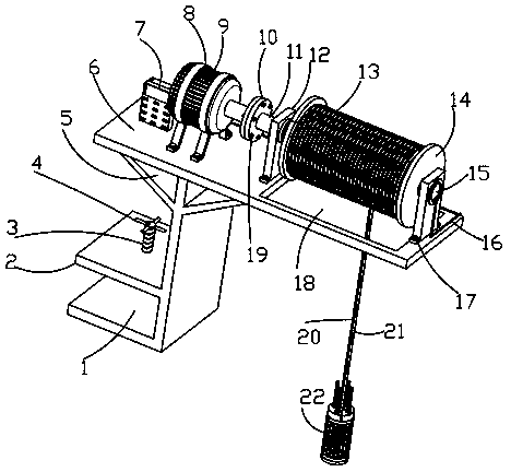
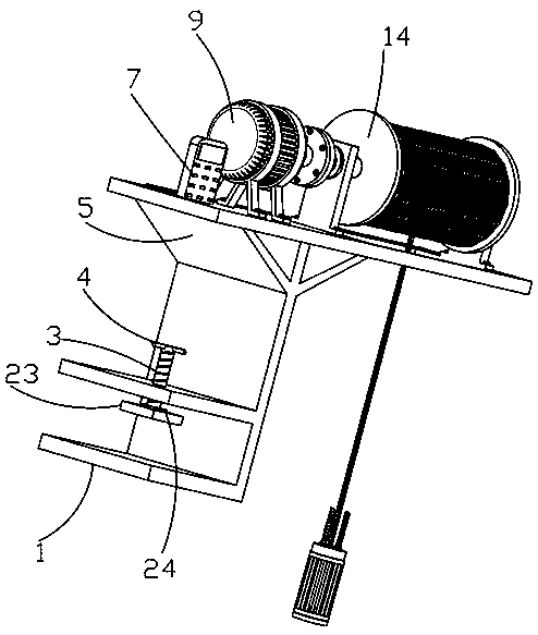
[0028] Such as Figure 1-4 The shown intelligent measuring device for water conservancy projects includes an L-shaped support plate 1, a measurement display panel 7, a drive motor 9, a conductive slip ring 15 and a liquid level sensor 28, and the middle end of the left side wall of the L-shaped support plate 1 A horizontal plate 2 is fixedly connected at the horizontal plate 2, and a fixed structure is provided on the horizontal plate 2. The fixed structure includes a compression threaded rod 3, a push rod 4, a second bearing 24 and a pressure plate 23. The threaded hole at the middle end of the horizontal plate 2 is connected with The compression threaded rod 3 is threadedly connected, the top of the compression threaded rod 3 is evenly fixedly connected with the push rod 4 along the circumferential direction, the bottom of the compression threaded rod 3 is fixedly connected with the inner ring of the second bearing 24, and the outer ring of the second bearing 24 It is fixedl...
Embodiment 2
[0030] Embodiment 2 is a further improvement to Embodiment 1.
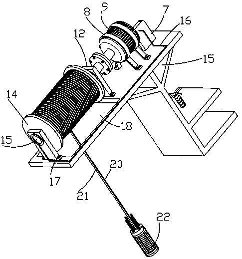
[0031] Such as Figure 1-4The shown intelligent measuring device for water conservancy projects includes an L-shaped support plate 1, a measurement display panel 7, a drive motor 9, a conductive slip ring 15 and a liquid level sensor 28, and the middle end of the left side wall of the L-shaped support plate 1 The horizontal plate 2 is fixedly connected with the horizontal plate 2, and a fixed structure is arranged on the horizontal plate 2. The L-shaped support plate 1 is fixedly connected with a mounting plate 5, and the top of the mounting plate 5 is provided with a measurement display panel 7, a mounting frame 8 and a supporting plate 12 in sequence from the left. , the mounting frame 8 is fixedly installed with a drive motor 9, the output end of the drive motor 9 is fixedly connected with a flange 10, and the first bearing 13 and a conductive slip ring 15 are respectively fixedly connected in the horizontal ho...
Embodiment 3
[0033] Such as Figure 1-4 The shown intelligent measuring device for water conservancy projects includes an L-shaped support plate 1, a measurement display panel 7, a drive motor 9, a conductive slip ring 15 and a liquid level sensor 28, and the middle end of the left side wall of the L-shaped support plate 1 The horizontal plate 2 is fixedly connected with the horizontal plate 2, and a fixed structure is arranged on the horizontal plate 2. The L-shaped support plate 1 is fixedly connected with a mounting plate 5, and the top of the mounting plate 5 is provided with a measurement display panel 7, a mounting frame 8 and a supporting plate 12 in sequence from the left. , the mounting frame 8 is fixedly installed with a drive motor 9, the output end of the drive motor 9 is fixedly connected with a flange 10, and the first bearing 13 and a conductive slip ring 15 are respectively fixedly connected in the horizontal hole of the support plate 12, and the conductive slip ring 15 The...
PUM
 Abstract
Description
Claims
Application Information