Magneto-optic diaphragm, magneto-optical sensor and weld joint detection device and method

A magneto-optical and sensor technology, used in measuring devices, instruments, scientific instruments, etc., can solve the problems of low quality of magneto-optical images and small illumination area of ​​light sources, so as to improve image quality, avoid mutual influence, and improve magneto-optical images. Effect of Resolution and Weld Defect Detection Accuracy

Active Publication Date: 2020-06-19
SHANDONG UNIV
View PDF10 Cites 2 Cited by
  • Summary
  • Abstract
  • Description
  • Claims
  • Application Information

AI Technical Summary

Problems solved by technology

[0007] The second object of the present invention is a magneto-optical sensor, which uses a line light source to solve the problems of low magneto-optical image quality and small illuminated area of ​​the light source

Method used


Image

  • Magneto-optic diaphragm, magneto-optical sensor and weld joint detection device and method
  • Magneto-optic diaphragm, magneto-optical sensor and weld joint detection device and method
  • Magneto-optic diaphragm, magneto-optical sensor and weld joint detection device and method

Examples


Embodiment 1

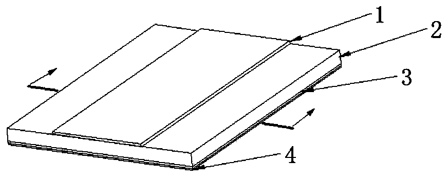
[0042] This embodiment provides a magneto-optical diaphragm to solve the problem of small Faraday rotation angle caused by the small thickness of the magneto-optical diaphragm.

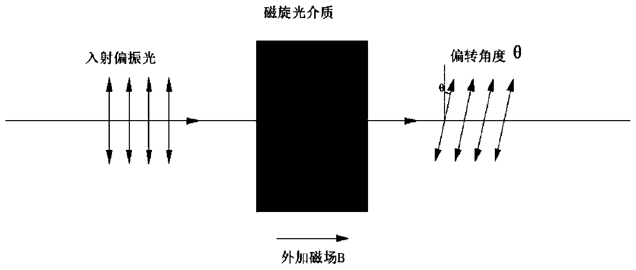
[0043] The principle of magneto-optical imaging is based on the Faraday magneto-optical rotation effect, such as figure 1As shown, the polarization direction of polarized light will rotate at a certain angle when passing through the optically active medium with an external magnetic field. This rotation angle is called the Faraday rotation angle θ. The magnetic induction intensity component B in the propagation direction of the light is proportional, that is:

[0044] θ=V×B×d

[0045] In the formula: V is a coefficient that characterizes the magneto-optical properties, which depends on the material properties of the magneto-optical medium and the working wavelength of the light, and is called the Verdet constant.

[0046] Such as figure 2 As shown, in the existing magneto-optical imaging detection ...

Embodiment 2

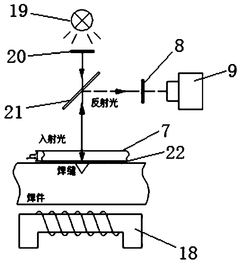
[0058] This embodiment provides a magneto-optical sensor, such as Figure 5 As shown, it includes housing 5, line laser emitter 6, analyzer 8, CCD camera 9 and the magnetic optical rotation diaphragm 7 described in Embodiment 1. Since the light emitted by line laser emitter 6 is polarized light, there is no need Polarizers convert light into polarized light. The casing 5 is a closed structure, and its interior is a cavity for installing a line laser emitter 6 , a polarizer 8 , a CCD camera 9 , and a magnetic-optical diaphragm 7 . In this embodiment, the housing 5 has a rectangular parallelepiped structure. It can be understood that in other embodiments, the housing 5 can also be in other shapes, such as spherical, as long as the above components can be installed and the installation position can be guaranteed.

[0059] In this embodiment, the magnetic optical rotation diaphragm 7 is fixed on the bottom surface of the housing 5, the line laser emitter 6 is located on one side ...

Embodiment 3

[0067] This embodiment provides a weld detection device, such as Figure 8 As shown, it includes a magnetic field generator 14, a linear motion device, a computer 17, a main control board 15 and the magneto-optical sensor 11 described in the second embodiment. To detect relative movement of the weld seam, a linear motion device is provided in this embodiment to move the weldment 12 relative to the magneto-optical sensor 11 .

[0068] The magneto-optical sensor 11 is arranged above the linear motion device, and the magneto-optic sensor 11 is connected to the computer 17 through wires. In this embodiment, the linear motion device includes a motion platform 13, a support, a lead screw and a motor 16, the lead screw passes through the support horizontally, and both ends of the lead screw are respectively connected to the support in rotation.

[0069] One end of the lead screw is connected to a motor 16 , which drives the lead screw to rotate; the motor 16 is connected to a comput...


PUM

PropertyMeasurementUnit
thicknessaaaaaaaaaa
thicknessaaaaaaaaaa

Abstract

The invention discloses a magneto-optic diaphragm, a magneto-optic sensor, a weld joint detection device and a weld joint detection method, thereby solving problems that in the prior art, the magneto-optical image quality is not high, the light source irradiation area is small, two-dimensional scanning is needed, and the welding seam defect detection precision is not high. The upper surface and the lower surface of the magneto-optic diaphragm are plated with reflecting films, a linear light source is used as a polarized light source, the detection precision and resolution of the magneto-opticsensor are enhanced, and the weld defect detection effect is improved. According to the technical scheme, the magneto-optic diaphragm comprises a magneto-optic dielectric layer; a first reflecting layer is arranged on one side of the magneto-optic dielectric layer, and a second reflecting layer is fixed to the other side of the magneto-optic dielectric layer; and the second reflecting layer cooperates with the first reflecting layer to increase the reflection times of the polarized light.

Description

technical field [0001] The invention belongs to the technical field of weld non-destructive testing, and in particular relates to a magneto-optical diaphragm, a magneto-optical sensor, a weld testing device and method. Background technique [0002] As one of the most important technologies in the manufacturing field, welding is closely related to the quality and service life of equipment. Since the working environment of weldments is mostly harsh, defects on welds will directly lead to damage to weldments, affecting the safety and life of equipment, so a non-destructive testing technology for detecting weld defects is of great significance. At present, the non-destructive testing techniques at home and abroad include magnetic particle testing, penetrant testing, radiographic testing and eddy current testing, etc., but the above testing methods all have certain limitations and deficiencies. [0003] In recent years, the welding seam detection technology based on the principl...

Claims


Application Information

Patent Timeline
Patent Type & Authority Applications(China)
IPC IPC(8): G01N21/21
CPCG01N21/21G01N2021/218
Inventor 李学勇高飞谢朝阳路长厚
Owner SHANDONG UNIV
Why Eureka
Try Eureka