
Optical fiber gravity gradiometer and gravity gradient measuring method

A gravitational gradiometer and gravitational gradient technology, which are used in measurement devices, gravitational field measurement, geophysical measurement, etc., to achieve the effects of fast transmission speed, rapid measurement, and improved detection accuracy

Active Publication Date: 2020-06-19
PEKING UNIV
View PDF8 Cites 2 Cited by
  • Summary
  • Abstract
  • Description
  • Claims
  • Application Information

AI Technical Summary

Problems solved by technology

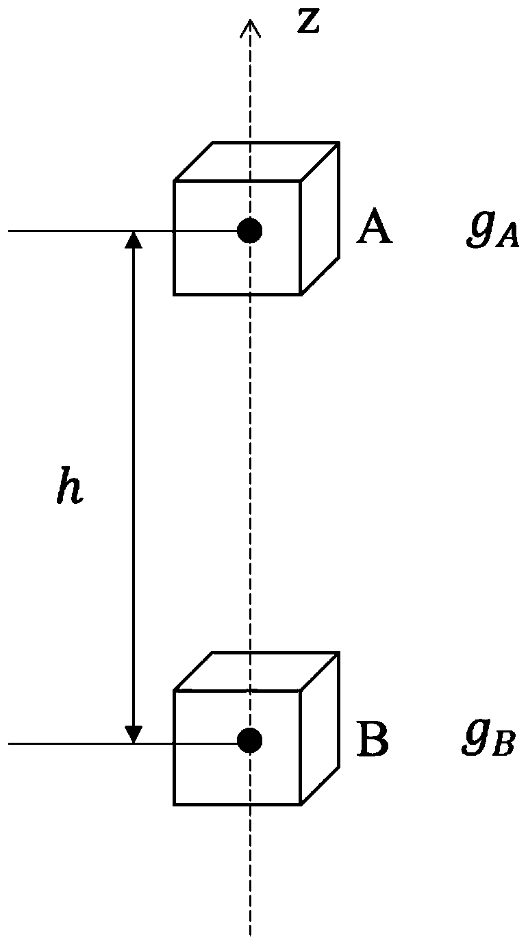
[0014] It can be seen from formula (3) that when the gravity gradient in the instrument space is not uniform, the gravity gradient obtained by the differential method is only the slope of the two-point secant line on the gravity curve, not the tangent slope of the gravity curve (that is, the gravity gradient); From a mathematical point of view, since the gravity gradient is the derivative of gravity, according to the Taylor expansion form, what the difference method obtains is only the first-order approximation of the gravity gradient, rather than the true value of the gravity gradient; in addition, since this method needs to use multiple Gravitational acceleration device, the consistency between various internal devices is an unavoidable problem

Method used


Image

  • Optical fiber gravity gradiometer and gravity gradient measuring method
  • Optical fiber gravity gradiometer and gravity gradient measuring method
  • Optical fiber gravity gradiometer and gravity gradient measuring method

Examples


Embodiment Construction

[0066] The present invention will be described in further detail below in conjunction with the accompanying drawings.

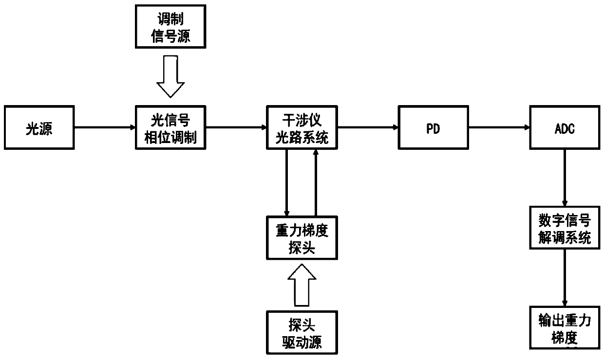
[0067] Fiber optic gravity gradiometer frame as attached figure 2 As shown, the signal light is excited from the light source, and the optical signal phase modulation is performed on the signal source by using a phase modulator (such as piezoelectric ceramics, Y waveguide integrated optical circuit device) to improve the anti-interference characteristics of the signal and reduce the influence of noise on the signal; after that Through the interferometer optical system and the gravity gradient probe, the probe is controlled by the driving source to vibrate in the vertical direction, and this vibration will produce a change in the amplitude due to the influence of the gravity gradient, thereby causing the signal light phase to be affected; through the PD (photodetector ) converts the signal light into an electrical signal, and converts it into a digital signal...


PUM


Abstract

The invention discloses an optical fiber gravity gradiometer and a gravity gradient measuring method. The optical fiber gravity gradiometer comprises an optical signal phase modulator, an interferometer optical path system, a photoelectric detector and an analog-to-digital converter. The interferometer optical path system is used for receiving modulated signal light output by the optical signal phase modulator and generating interference. An interference light path of the interferometer light path system is provided with an optical fiber gravity gradient probe, the optical fiber gravity gradient probe is connected with a driving source, and the driving source is used for controlling the optical fiber gravity gradient probe to vibrate in the vertical direction, so that the phase of signal light in the light path where the optical fiber gravity gradient probe is located is changed; the photoelectric detector is used for receiving the signal light output by the interferometer light path system and converting the signal light into an electric signal; and the analog-to-digital converter converts the electric signal into a digital signal and sends the digital signal to a demodulation system for resolving to obtain a gravity gradient. According to the invention, the detection requirement of gravity gradient can be greatly reduced, and the gravity gradient can be rapidly and accuratelymeasured.

Description

technical field [0001] The invention relates to an optical fiber gravity gradient meter and a gravity gradient measurement method, which can be used for satellite, aviation, land and underwater earth gravity gradient field measurement, and are also suitable for mineral resource development, geological and geophysical exploration, geothermal field monitoring, geological Disaster early warning, research on the deep structure of the earth, oceanography and climatology, inertial navigation, military anti-submarine and other engineering and scientific research fields. Background technique [0002] There are many geophysical fields in the earth's space, and the earth's gravitational field is one of them. The basic physical field quantity of this field is the acceleration of gravity, generally with the symbol express. [0003] According to the general relationship between a force and its corresponding potential, the acceleration due to gravity Equal to the gradient of the grav...

Claims


Application Information

Patent Timeline
IPC IPC(8): G01V7/00G01V7/04
CPCG01V7/00G01V7/04
Inventor 陈炳吉陈彦钧李正斌
Owner PEKING UNIV
Learn More