

Full push magnetic repulsion type automatic magnetic levitation system
A magnetic levitation and automatic technology, applied in the direction of the magnetic attraction or thrust holding device, electrical components, etc., can solve the problems of automatic magnetic levitation, large size, high device height, etc., and achieve stable magnetic levitation effect and compression thickness , the effect of saving space
- Summary
- Abstract
- Description
- Claims
- Application Information
AI Technical Summary
Problems solved by technology
Method used
Image

Examples
Embodiment 1
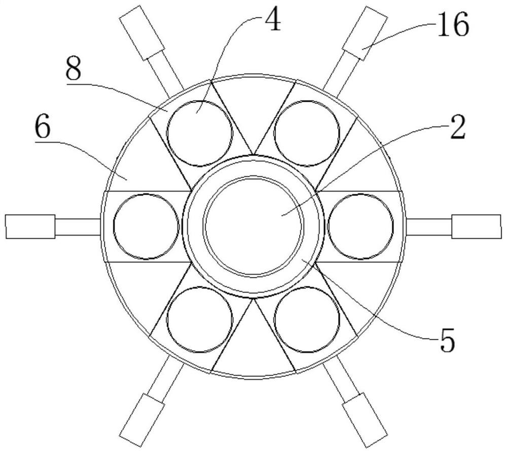
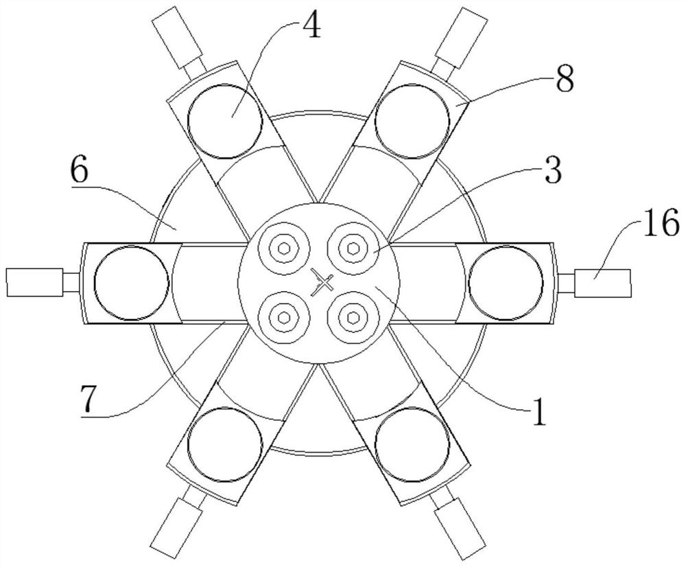
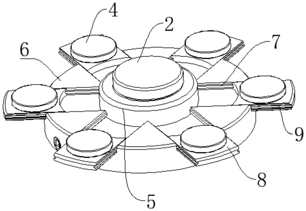
[0034] Embodiment one: if Figure 1-3 As shown, the present invention provides an all-position pushing magnetic repulsion type automatic magnetic levitation system, comprising a base plate 1, a magnetic base and a suspension body 2, the magnetic base includes four electromagnets 3 and six permanent magnets 4, of which four The four electromagnets 3 are evenly distributed on the central axis of the base, the suspension 2 is arranged above the center of the four electromagnets 3 through a stable base 5, and the six permanent magnets 4 are evenly distributed on the center of the four electromagnets 3 through corresponding sliding components. The outer edges of the four electromagnets 3, the sliding assembly moves linearly along the direction perpendicular to the central axis of the base by pushing the assembly.
[0035] The bottom plate 1 is a circular iron sheet, on which an integrated circuit board is arranged, and the integrated circuit board is connected with the electromagne...
Embodiment 2
[0037] Embodiment two, such as Figure 4 As shown, on the basis of the first embodiment, in order to further ensure the synchronization of the six permanent magnets 4, the drive of the six cylinders 16 is changed to the drive of one servo motor 13. Specifically: the pushing assembly includes a rotating disk 10 , the upper surface of the rotating disk 10 is provided with a thread 11 , and the bottom of the slider 8 is provided with a threaded groove 12 matching the thread 11 on the rotating disk 10 . The rotating disk 10 is connected with a driving assembly for driving the rotating disk 10 to rotate. The drive assembly is a servo motor 13, and the rotating disk 10 is connected to the servo motor 13 through gears.
[0038]That is, the rotating disk 10 is arranged coaxially with the bearing platform 6, and the rotating disk 10 can rotate around the center of the bearing platform 6 on the bearing platform 6 through the annular slide rail 7 or the chute 9, while the slider 8 is ar...
Embodiment 3
[0039] Embodiment three, such as Figure 5-9 As shown, on the basis of Embodiment 2, in order to further ensure the synchronization of the six permanent magnets 4 and the stability of the rotating disk 10, the gear is a bevel gear 14, and the lower surface of the rotating disk 10 is provided with a conical Thread teeth 15, the tapered thread teeth 15 are adapted to the bevel gear 14. Conical threaded teeth 15, that is, the lower surface of the rotating disk 10 is conical shaped to match the taper of the bevel gear 14, and the threaded teeth on the lower surface of the rotating disk 10 are adapted to the teeth of the bevel gear 14.
[0040] That is, the conventional gear drive between the rotating disk 10 and the servo motor 13 is changed to bevel gear 14 driving, and the bevel gear 14 connected to the servo motor 13 is meshed with the conical threaded teeth 15 provided on the lower surface of the rotating disk 10. To further ensure the smoothness of the operation of the rotat...
PUM
 Abstract
Description
Claims
Application Information