
Single-power-supply gate pole edge controllable driving circuit

A driving circuit and single power supply technology, applied in high-efficiency power electronic conversion, electronic switches, electrical components, etc., can solve gate resistance, complex gate drive power supply circuit, inability to continuously control gate edge voltage, and complex power supply circuit structure and other issues, to achieve the effect of simplifying the design of the driving power supply and simplifying the gate edge control circuit

Active Publication Date: 2020-06-19
NR ENG CO LTD +1
View PDF3 Cites 0 Cited by
  • Summary
  • Abstract
  • Description
  • Claims
  • Application Information

AI Technical Summary

Problems solved by technology

The control of the driving gate voltage edge usually adopts the methods of hierarchical driving resistance and multi-level voltage source. This kind of gate edge control method has complex gate resistance and gate driving power supply circuits, and cannot continuously control the gate edge voltage. For different Power switching devices need to change hardware circuit parameters, and the adaptability is not high
[0005] Chinese patent application number 201510222407.3 discloses an adjustable control circuit for the rising and falling edge voltage of the IGBT drive gate. The control, control and power circuit structure is complex, and the gate level cannot be continuously adjusted

Method used


Image

  • Single-power-supply gate pole edge controllable driving circuit
  • Single-power-supply gate pole edge controllable driving circuit
  • Single-power-supply gate pole edge controllable driving circuit

Examples


Embodiment Construction

[0020] The present invention will be further described below in conjunction with accompanying drawing.

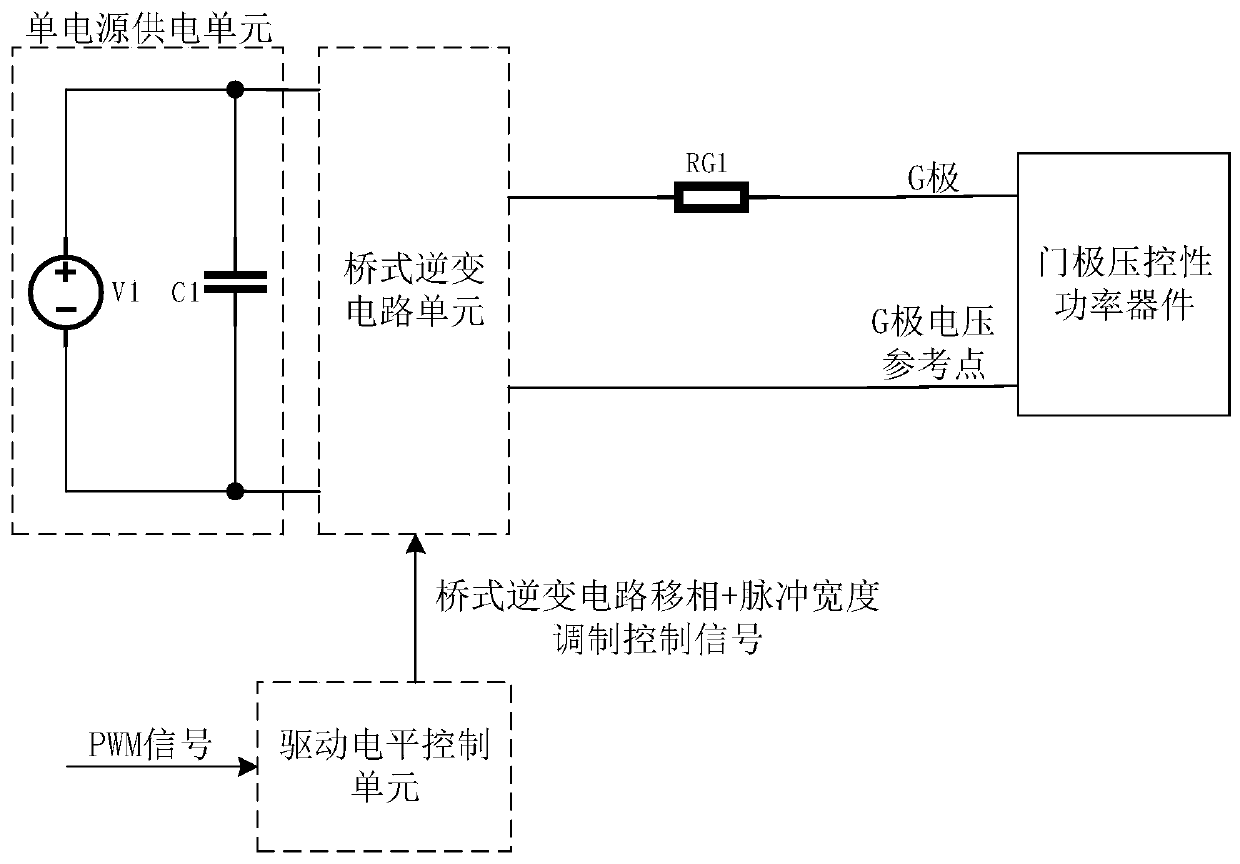
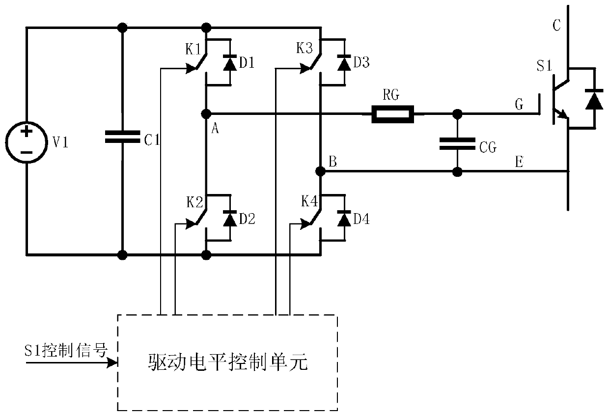
[0021] Combined with the principle of the present invention figure 1 ,by figure 2 A specific implementation of a single power supply gate edge controllable drive circuit will be described as an example.

[0022] The single power supply unit is composed of driving power supply voltage V1 and DC energy storage capacitor C1; the bridge unit is a full bridge circuit composed of controllable electronic switches K1~K4 and anti-parallel diodes D1~D4; the capacitor of the single power supply unit C1 is connected with the bridge unit to provide power supply power.

[0023] The output terminals A and B of the bridge unit are connected to the driven power switching device S1 through the gate resistor RG, and S1 is an IGBT. CG is the gate equivalent capacitance of S1, which is connected in parallel with the G pole and E pole of S1.

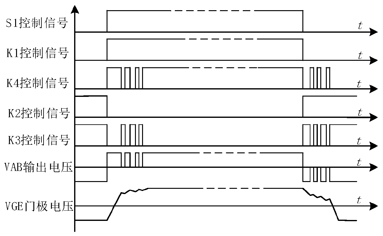
[0024] refer to image 3 , the control flow st...


PUM


Abstract

The invention discloses a single-power-supply gate pole edge controllable driving circuit. A single power supply is adopted; a bridge circuit is used for supplying power to gate poles of the power devices respectively; positive voltage and zero voltage are applied to a gate pole reference point (such as an emitting electrode of an IGBT, a source electrode of an MOSFET and the like); the control ofpositive, zero and negative voltages of the grid is realized by utilizing the voltage difference between two points, and different positive, negative and zero voltage pulse widths of the opening andclosing edges of the grid are realized by phase shift and pulse width modulation of each switching tube of the bridge circuit in driving, so that the control of the opening and closing speeds and characteristics of the power device is realized. According to the invention, a single power supply is adopted, a two-level or multi-level bridge circuit is utilized to realize level change of driving voltage, and control of the edge rate and switching characteristics of the driving gate of the power device is realized.

Description

technical field [0001] The invention relates to a controllable drive circuit for a gate edge of a single power supply, and belongs to the technical field of power electronic power switch device drive. Background technique [0002] In recent years, gate voltage-controlled power switching devices such as IGBT, MOSFET, and SiC have been widely used. The electrical characteristics of these power switching devices at the switching moment are the prerequisites for their safe operation. Improving the electrical characteristics at the switching moment can significantly improve the operational reliability of the power switching device. [0003] IGBT, MOSFET, especially some new SiC power switching devices, the switching time is extremely short, the switching rate is extremely fast, due to the parasitic capacitance and inductance in the device and circuit, the high voltage and current change rate at the time of switching, often in the power switch The voltage and current oscillations...

Claims


Application Information

Patent Timeline
Patent Type & Authority Applications(China)
IPC IPC(8): H03K17/56H03K17/567H03K17/687H02M1/08H02M7/5387
CPCH03K17/56H03K17/567H03K17/687H02M1/08H02M7/53871Y02B70/10
Inventor 张茂强汪涛虞晓阳李乐乐李汉杰文继锋曹冬明
Owner NR ENG CO LTD
Learn More