
Molten steel atomizing disc, atomizing and pelleting equipment and atomizing and pelleting method

A technology of atomizing disc and molten steel, which is applied in the field of stainless steel shot atomizing and spraying disc, can solve the problems of reducing the proportion of fine particle steel shot and affecting the blowing degree of molten steel, so as to achieve large spraying volume, prevent metal oxidation, and prevent steel shot The effect of high yield

Inactive Publication Date: 2020-06-23
无锡锋速钢丸有限公司
View PDF10 Cites 1 Cited by
  • Summary
  • Abstract
  • Description
  • Claims
  • Application Information

AI Technical Summary

Problems solved by technology

[0004] In the above structure, the gas is input into the annular air gap between the upper spray plate and the lower spray plate through the air inlet, and after the gas is output from the annular air gap, the molten steel can be blown away theoretically to form steel shots; but the actual operation process When the gas is output from the annular air slit, the velocity and direction of the airflow will affect the blowing degree of the molten steel. If the velocity of the airflow is not fast enough, the molten steel may be reduced due to bonding before the molten steel is completely cooled. Ratio of fine particle steel shot

Method used


Image

  • Molten steel atomizing disc, atomizing and pelleting equipment and atomizing and pelleting method
  • Molten steel atomizing disc, atomizing and pelleting equipment and atomizing and pelleting method
  • Molten steel atomizing disc, atomizing and pelleting equipment and atomizing and pelleting method

Examples


Embodiment 1

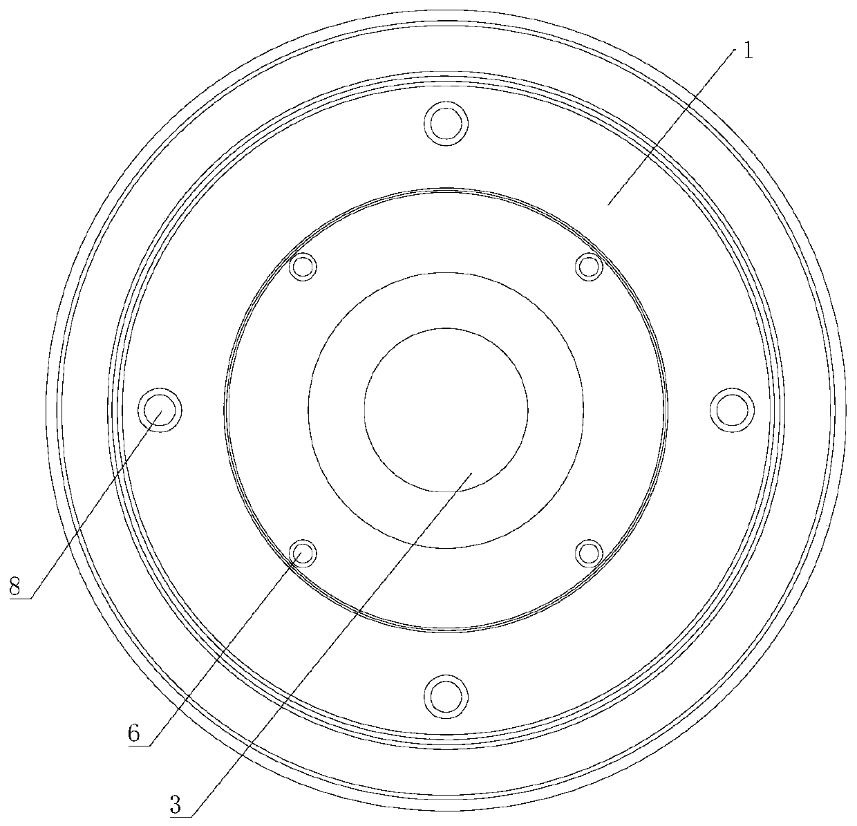
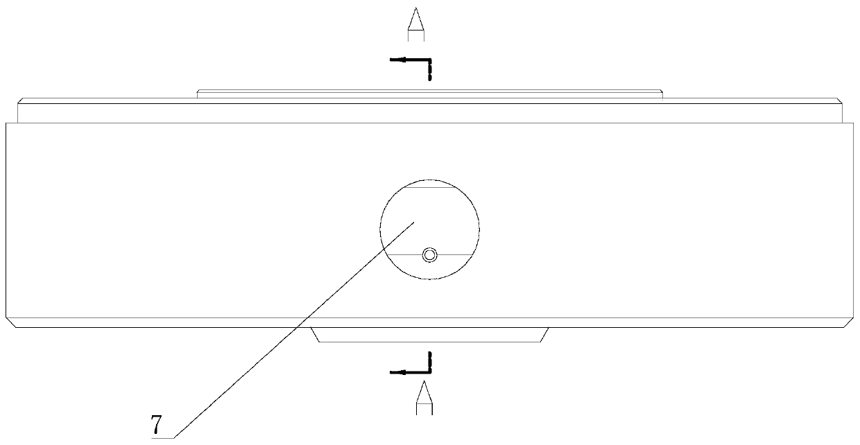
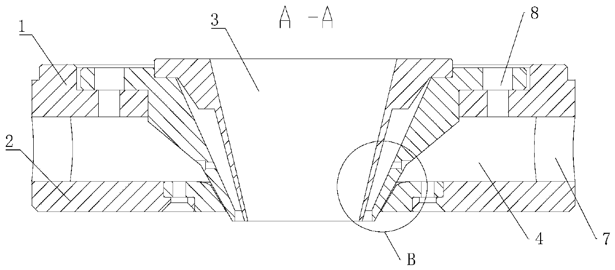
[0027] A molten steel atomization disc, such as figure 1 with 3 As shown, the upper spray plate 1 and the lower spray plate 2 are coaxially arranged. In this embodiment, the upper spray plate 1 and the lower spray plate 2 are both set as circular metal plates, and the upper spray plate 1 and the lower spray plate 2 are Both cone holes 3 are provided, and the two cone holes 3 are coaxial with the upper spray plate 1 and the lower spray plate 2. The cone hole 3 of the upper spray plate 1 falls in the cone hole 3 of the lower spray plate 2. Between the upper spray plate 1 and the lower spray plate 2 are reserved an air cavity 4 allowing air flow to pass, and a Laval structure annular gap 5 connected to the air cavity 4. The air cavity 4 is arranged as an annular hollow cavity, and is arranged coaxially with the upper spray plate 1 and the lower spray plate 2. Such as Figure 4 As shown, the air cavity 4 is close to the center axis of the upper spray plate 1 or the lower spray pla...

Embodiment 2

[0035] A kind of atomized pelletizing equipment, mainly used to manufacture steel shot or steel grit, including the equipment body. The equipment body is provided with an air inlet and a molten steel inlet. For the equipment using the molten steel atomizing disc in embodiment 1 In other words, except for the air inlet, the molten steel inlet, and the molten steel atomizing plate, the necessary components are no different from conventional molten steel output equipment. The air inlet is communicated with the air inlet 7 and is used to input nitrogen into the air inlet 7. As an optimized structure, it can also communicate with the air supplement hole 6 to facilitate the input of gas through the air supplement hole 6. The molten steel inlet is communicated with the cone hole 3 on the upper spray plate 1 and is used to input the molten steel to be atomized into the cone hole 3.

[0036] In this embodiment, the nitrogen output from the air inlet of the atomizing pelletizing equipment ...

Embodiment 3

[0038] An atomized pelletizing method employs the molten steel atomizing disk in Example 1 and the atomized pelletizing equipment in Example 2. Including the following steps:

[0039] S1: Input high-pressure atomized inert gas into the inlet 7; the inert gas in this embodiment is nitrogen, and the nitrogen enters from the inlet 7 on both sides of the upper and lower spray discs 2, which is formed by the linear inlet 7 Enter the air cavity 4 in a tangential direction. After the airflow from the air inlets 7 on both sides enters the air cavity 4, it has a tangential acceleration. The airflow in the air cavity 4 flows in the annular air cavity 4 and is also output to the narrow throat. It is more convenient to form a conical air vortex.

[0040] S2: Input molten metal into the cone 3 of the upward spray plate 1;

[0041] It should be noted that the liquid metal does not start to be input until the airflow enters the air inlet 7 and forms a conical cyclone, so that the liquid metal can...


PUM

PropertyMeasurementUnit
diameteraaaaaaaaaa

Abstract

The invention discloses a molten steel atomizing disk, atomizing and pelleting equipment and a atomizing and pelleting method. The molten steel atomizing disc comprises an upper spraying disc body anda lower spraying disc body which are coaxially arranged, conical holes are formed in the upper spraying disc body and the lower spraying disc body correspondingly, an air cavity allowing airflow to pass through and a Laval structure annular gap connected with the air cavity are reserved between the upper spraying disc body and the lower spraying disc body, and the narrow throat of the Laval structure annular gap is located on one side, away from the air cavity, of the Laval structure annular gap. Gas passes through the annular gap of the spraying disc, namely a Laval structure, the gas is accelerated and ejected at high speed; and due to the fact that an included angle is formed between the path through which the gas passes in the spraying process and the central axis of the upper spraying disc body and the central axis of the lower spraying disc body, and the gas cavity and the Laval structure gap which communicates with the gas cavity are both annular, the gas forms a vortex-closedgas cone after being sprayed out through the narrow throat, and molten metal flowing through the cone top is crushed, the gas injection amount is large and uniform, and the steel shot yield is high.

Description

Technical field [0001] The invention relates to a molten steel atomization disc, an atomization pill making device and an atomization pill making method, belonging to the technical field of stainless steel shot atomization spray discs. Background technique [0002] The spray disc is a common component used to produce steel shot, including the upper spray disc and the lower spray disc. There is a flow channel between the upper spray disc and the lower spray disc that allows the molten steel to flow through. When the molten steel flows through the flow channel, it is located An air flow is introduced into the gap between the upper spray plate and the lower spray plate, and the output direction of the air flow is toward the molten steel, and the molten steel is blown and cooled to obtain steel shots. [0003] At present, the Chinese Patent Authorized Announcement No. CN208483226U discloses a stainless steel shot atomized spray disc, including a lower spray disc, an upper spray disc, a...

Claims


Application Information

Patent Timeline
Patent Type & Authority Applications(China)
IPC IPC(8): B22F9/08
CPCB22F9/082B22F2009/086
Inventor 王霆俞瑶希倪雅汇
Owner 无锡锋速钢丸有限公司
Learn More