Photo-curing 3D printing equipment and image exposure system thereof

A technology of 3D printing and exposure system, applied in the field of image exposure system, can solve problems such as limited application

Pending Publication Date: 2020-06-23
PRISMLAB CHINA
View PDF0 Cites 0 Cited by
  • Summary
  • Abstract
  • Description
  • Claims
  • Application Information

AI Technical Summary

Problems solved by technology

When LCOS is applied in 3D printing, the resolution limit restricts its development. For example, the highest resolution commonly used by current LCOS is usually 1920*1080
However, this resolution can only produce objects with an area of ​​192*108mm with the commonly used 0.1mm precision in 3D printing, which obviously limits its application

Method used


Image

  • Photo-curing 3D printing equipment and image exposure system thereof
  • Photo-curing 3D printing equipment and image exposure system thereof
  • Photo-curing 3D printing equipment and image exposure system thereof

Examples


Embodiment Construction

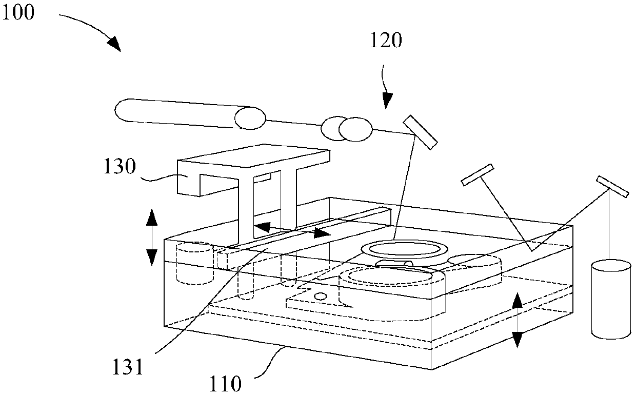
[0063] The embodiment of the present invention describes a 3D printing device and its image exposure system, and the image exposure system uses a silicon-based liquid crystal panel as an area array image source.

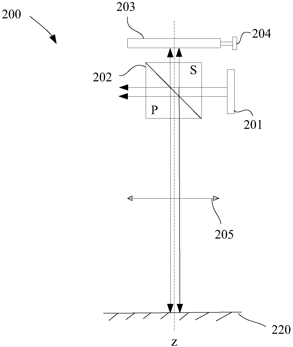
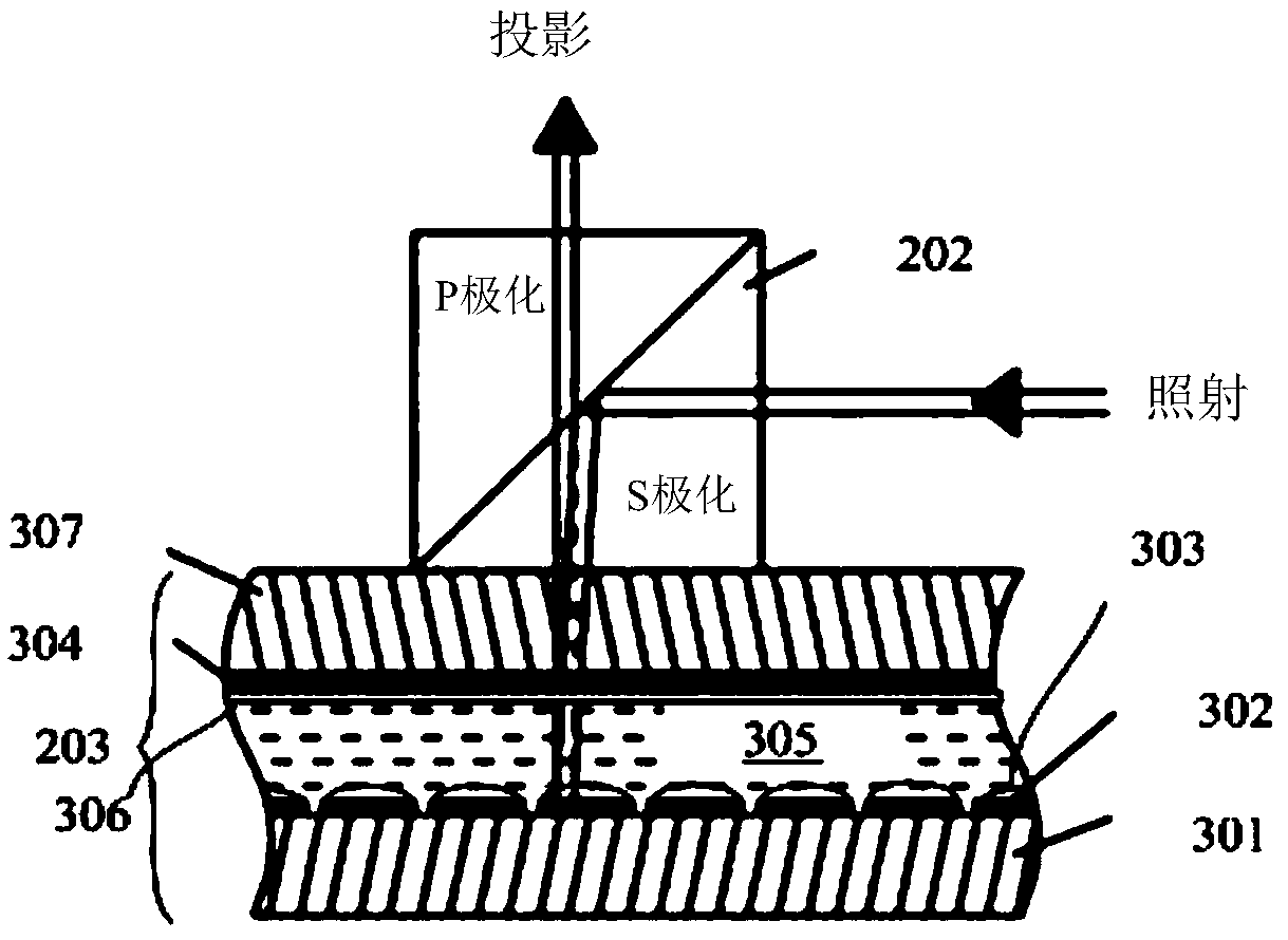
[0064] figure 2 An image exposure system of a 3D printing device according to an embodiment of the present invention is shown. refer to figure 2 As shown, the image exposure system 200 of this embodiment includes a light source 201, a polarizing beam splitter prism 202, a liquid crystal on silicon (LCOS) panel 203, a micro-displacement mechanism 204, a projection lens 205 and a controller (not shown). For the sake of clarity, components not relevant to the present invention are not shown.

[0065] The light source 201 is used to generate light beams to be irradiated onto the LCOS panel 203 . The wavelength of the light emitted by the light source 201 depends on the cured photosensitive material. For example, when UV resin is selected as the photosensitive mater...


PUM


Abstract

The invention relates to a 3D printing equipment image exposure system. A silicon-based liquid crystal panel is adopted as an area array image source. The silicon-based liquid crystal panel comprisesa mirror electrode array, a common electrode, a liquid crystal located between the mirror electrode electrode array and the common electrode, a first alignment film located between the mirror electrode array and the liquid crystal, and a second alignment film located between the liquid crystal and the common electrode. The first alignment film protrudes at the first mirror electrode of the corresponding mirror electrode array to form a focusing lens. Each focusing lens can converge light irradiated to the corresponding mirror electrode, and therefore the size of the micro facula reflected by the mirror electrode is smaller than the pixel size corresponding to the mirror electrode, the silicon-based liquid crystal panel is used for adjusting the state of the liquid crystal according to thecontrol signal, and therefore the polarization direction of each light reflected by the mirror electrode array is changed.

Description

technical field [0001] The invention relates to photocurable 3D printing equipment, in particular to an image exposure system of photocurable 3D printing equipment. Background technique [0002] 3D printing technology is based on the computer three-dimensional design model, through the software layered discrete and numerical control forming system, using laser beams, hot-melt nozzles, etc. to accumulate metal powder, ceramic powder, plastic, cell tissue and other special materials layer by layer Bonding, and finally overlaying and molding to create a solid product. Unlike the traditional manufacturing industry, which shapes and cuts raw materials through mechanical processing methods such as moulds, turning and milling to finally produce finished products, 3D printing transforms a three-dimensional entity into several two-dimensional planes. The manufacturing complexity is reduced. This digital manufacturing mode does not require complex processes, huge machine tools, or a...

Claims


Application Information

Patent Timeline
IPC IPC(8): B29C64/129B29C64/20B29C64/264B33Y10/00B33Y30/00
CPCB29C64/129B29C64/20B29C64/264B33Y10/00B33Y30/00G03F7/22
Inventor 侯锋
Owner PRISMLAB CHINA
Why Eureka
Try Eureka