Hybrid power driving system and vehicle

A technology of hybrid power and drive system, which is applied to the arrangement of multiple different prime movers of power devices, pneumatic power devices, and general power devices, and can solve the problem of high cost

Active Publication Date: 2020-06-23
GUANGZHOU AUTOMOBILE GROUP CO LTD
View PDF6 Cites 1 Cited by
  • Summary
  • Abstract
  • Description
  • Claims
  • Application Information

AI Technical Summary

Problems solved by technology

However, this system requires two independent subsystems, and the cost is high

Method used


Image

  • Hybrid power driving system and vehicle
  • Hybrid power driving system and vehicle
  • Hybrid power driving system and vehicle

Examples


Embodiment Construction

[0042] In order to make the object, technical solution and advantages of the present invention clearer, the implementation manners of the present invention will be further described below in conjunction with the accompanying drawings.

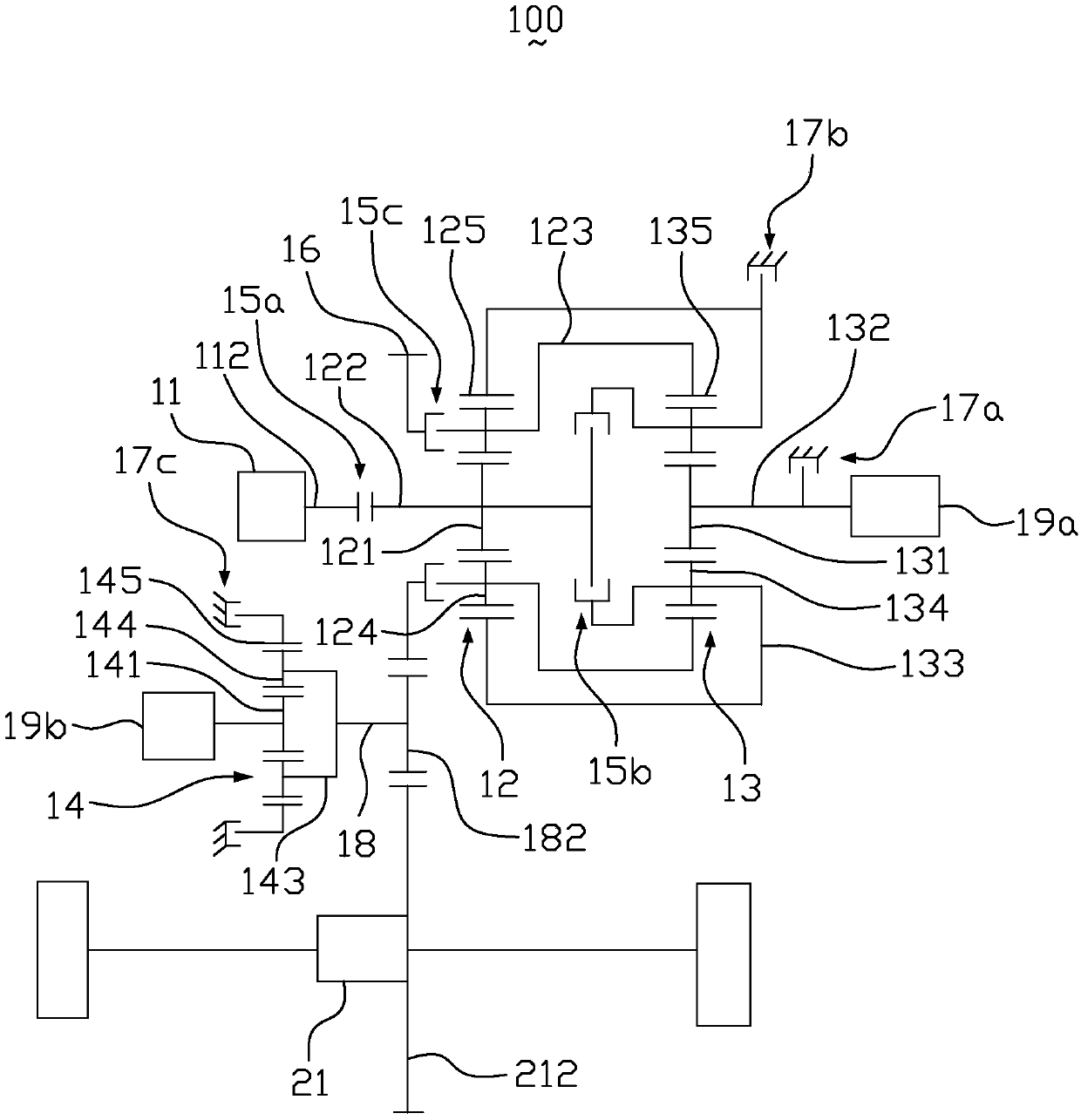
[0043] figure 1 It is a structural schematic diagram of the hybrid drive system according to the first embodiment of the present invention. Such as figure 1 As shown, the hybrid drive system 100 includes an engine 11, a first planetary gear device 12, a second planetary gear device 13, a third planetary gear device 14, a first clutch 15a, a second clutch 15b, a third clutch 15c, a power output Gear 16, first braking device 17a, second braking device 17b, third braking device 17c, intermediate shaft 18, first motor 19a, second motor 19b, differential 21 and power battery (not shown) .

[0044] The engine 11 has an engine output shaft 112 . In this embodiment, the engine 11 is, for example, a gasoline engine 11 or a diesel engine 11 .

[004...


PUM


Abstract

The invention relates to a hybrid power driving system. According to the hybrid power driving system, a first planetary gear device includes a first sun gear, a first planet carrier, and a first ringgear; an engine is provide with an engine output shaft; a first clutch for connecting the engine output shaft with a first sun gear shaft; a second planetary gear device comprises a second sun gear, asecond planet carrier and a second gear ring; the second sun gear is provided with a second sun gear shaft; the second sun gear shaft is connected with a first motor; the first planet carrier is connected with the second gear ring; the second planet carrier is connected with the first gear ring; a second clutch is used for connecting the first sun gear shaft with the second planet carrier; a third clutch is used for connecting the first planet carrier with a power output gear; the power output gear is connected with an intermediate shaft and outputs power to a wheel end through the intermediate shaft; a first braking device is used for braking the second sun gear; a second braking device is used for braking the first gear ring and the second planet carrier; and a second motor is connectedwith the intermediate shaft and outputs power to the wheel end through the intermediate shaft. The invention also relates to a vehicle.

Description

technical field [0001] The invention relates to the technical field of new energy, in particular to a hybrid power drive system and an automobile. Background technique [0002] The powertrain consists of the engine (internal combustion engine) and a drive train consisting of a transmission, differential and drive shaft. Its function is to provide the vehicle with the driving power required to drive the wheels. Internal combustion engines have a range of speeds and torques, and they work best within a small range where either fuel consumption is minimized, harmful emissions are minimized, or both. However, the actual road conditions are ever-changing, not only in the speed of the driving wheels, but also in the torque required by the driving wheels. Therefore, it is the primary task of the transmission to realize the optimal speed and torque of the internal combustion engine, that is, the optimal state of power, and a good match with the power state of the drive wheel. [...

Claims


Application Information

Patent Timeline
Patent Type & Authority Applications(China)
IPC IPC(8): B60K6/365B60K6/547
CPCB60K6/365B60K6/547
Inventor 李罡祁宏钟张安伟赵江灵尚阳杨洋徐明艳任晓华
Owner GUANGZHOU AUTOMOBILE GROUP CO LTD
Why Eureka
Try Eureka