Portal type aluminium bar stacking and unstacking unit

A gantry type and stacking technology, applied in the field of gantry type aluminum bar stacking and depalletizing units, can solve the problems of inconvenient maintenance of the stacking unit, affecting the overall aesthetics of the workshop, affecting the layout of the stacking units, etc. Manual operation and maintenance, easy maintenance of mechanical equipment, good economic and social benefits

Pending Publication Date: 2020-06-23
灿琛智能科技(上海)股份有限公司
View PDF0 Cites 0 Cited by
  • Summary
  • Abstract
  • Description
  • Claims
  • Application Information

AI Technical Summary

Problems solved by technology

[0005] In view of the above-mentioned shortcomings of the prior art, the object of the present invention is to provide a gantry-type aluminum bar stacking and depalletizing unit, which is used to solve the problem that the frame column in the prior art is the only shortcoming of the factory layout, and the frame The column needs to support the weight of the palletizing unit, the mechanical gripper and the aluminum rods of each layer. The column has a large cross section and a large number of columns. It is arranged in the middle of the workshop, which affects the overall aesthetic feeling of the workshop. At the same time, the existence of the column affects the yard The layout of the stations in the palletizing unit needs to consider the interference between the frame column and the three-position composite car that takes the material from the homogeneous furnace; the maintenance of the palletizing unit with a frame structure is inconvenient, and the electric control cabinet needs to be installed on the high-altitude palletizer ;Electrical failures in production, such as alarm reset, etc. need to be manually repaired from the stairs at one end of the workshop, including daily maintenance of mechanical work

Method used


Image

  • Portal type aluminium bar stacking and unstacking unit
  • Portal type aluminium bar stacking and unstacking unit

Examples


Embodiment 1

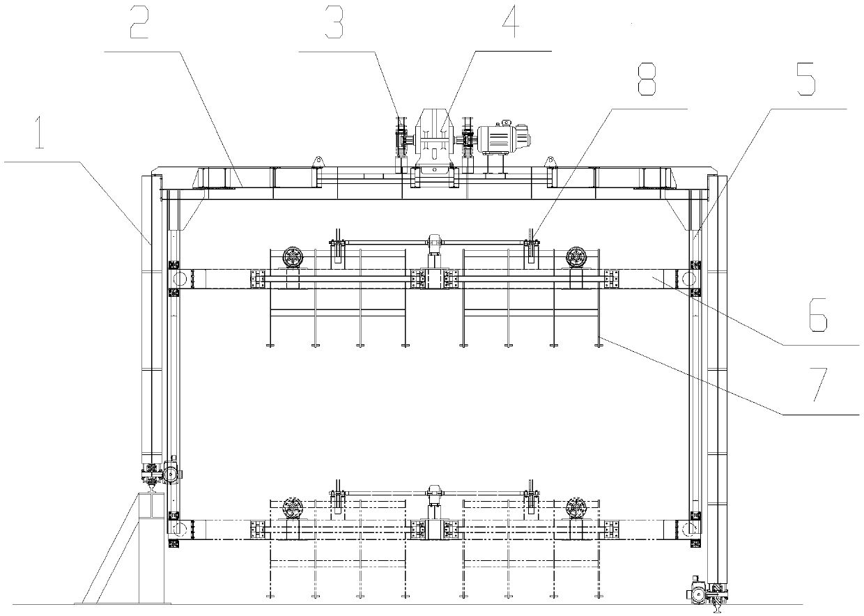
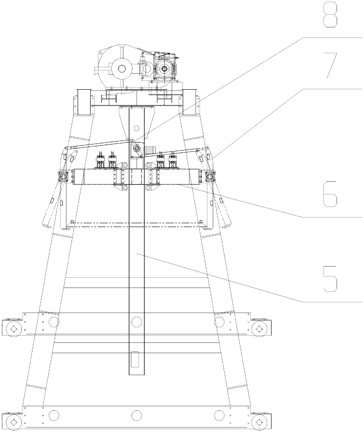
[0029] Embodiment 1. The lifting control device mainly has a fairly complete detection and control logic relationship in electricity. The normal lifting height position is different every time. According to the actual working state, the system calculates the height position that needs to be reached in the next step. The calculation record data of this position is given by the encoder; but in order to prevent the encoder from malfunctioning , and added laser ranging to verify the actual position information that should be reached; if the information given by the two exceeds the set value, the lifting control device will alarm, and the braking equipment is waiting for manual maintenance. The communication completes the transmission;

[0030] An infrared detection obstacle is installed under the traveling mechanism to prevent the gantry frame from colliding with sundries and personnel; when the obstacle is removed, the electronic control system will automatically start after 5 se...


PUM


Abstract

The invention provides a portal type aluminium bar stacking and unstacking unit. A stacking host machine is arranged between two transverse beams at the top of a portal frame and is composed of a lifting driving mechanism, a safety brake device and a lifting control device; lifting guide rails in bilateral symmetry are arranged on the inner sides of landing legs on the two sides of the portal frame, are vertically arranged, and are positioned on a center line between the two transverse beams on the top of the portal frame; a lifting platform is arranged between the lifting guide rails on the two sides; a dual-output motor is arranged in the middle of the lifting platform; a plurality of groups of symmetrical mechanical grippers are arranged on the left and right sides of the dual-output motor; any group of mechanical grippers is composed of gripper plates symmetrically arranged; and to-be-extracted material is arranged between the front gripper plate and the rear gripper plate of eachof the mechanical gripper. The portal type aluminium bar stacking and unstacking unit solves the problem that a frame stand column is interfered with three composite skip cars of a homogenizing furnace, does not need a frame, greatly saves the steel use level and facilitates manual operation and overhauling.

Description

technical field [0001] The invention belongs to the technical field of special equipment for the metallurgical industry, in particular to a gantry-type aluminum rod palletizing and depalletizing unit. Background technique [0002] At present, the diameter of aluminum rods on the market is getting thicker and thicker, and the diameter range: 5 inches to 17 inches is very common. The previous manual palletizing alone is far from meeting the actual production needs, and it is completed by manual lifting or forklift handling. ; The placement and recycling of the partitions are basically done manually, the degree of automation is very low, the labor intensity is high, and there are many factors such as potential safety hazards. With the increasingly strong demand for aluminum bar palletizing, several companies have tried to use some manipulators to partially replace manual labor. The effect is not very satisfactory, the efficiency is low, and it is not easy to operate. Some of th...

Claims


Application Information

Patent Timeline
Patent Type & Authority Applications(China)
IPC IPC(8): B66C19/00B66C1/22B66D1/12
CPCB66C1/22B66C19/00B66D1/12
Inventor 渠立强
Owner 灿琛智能科技(上海)股份有限公司
Why Eureka
Try Eureka