Battery top cover reinforcing structure
A technology to strengthen the structure and top cover, applied in the direction of battery cover/end cover, structural parts, battery pack components, etc., can solve the problems of crushed top cover, damaged cell, exposed cell, etc., to reduce pressure damage risk, facilitate large-scale promotion and use, and enhance the effect of carrying capacity
- Summary
- Abstract
- Description
- Claims
- Application Information
AI Technical Summary
Problems solved by technology
Method used
Image
Examples
no. 1 example
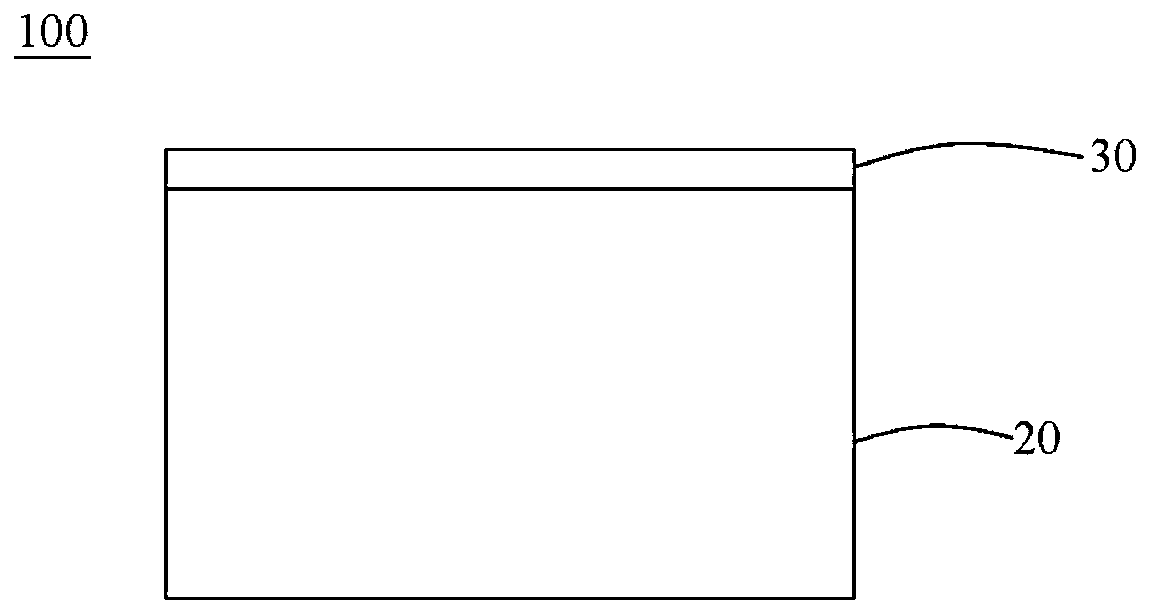
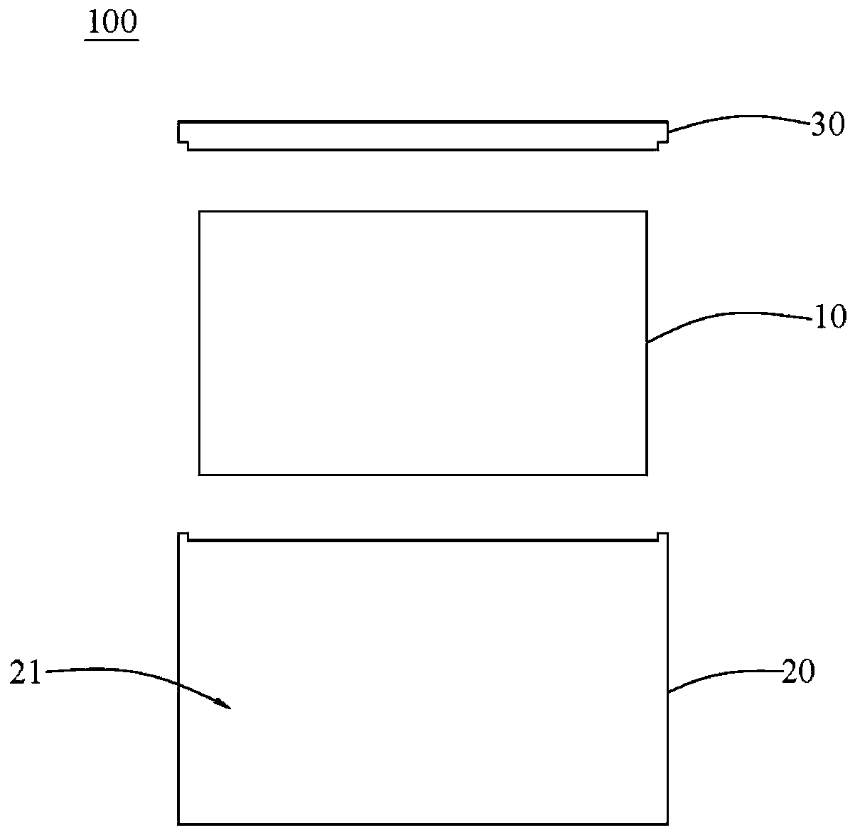
[0027] see figure 1 and figure 2 As shown, the power battery pack 100 of this embodiment includes a battery body 10, a casing 20 and a battery top cover reinforcement structure, wherein the casing 20 is a hollow structure with an open upper end, and the hollow structure forms a battery for storing the battery body 10. In the warehouse 21, the top cover body 30 is detachably covered on the opening of the housing 20. Preferably, the covering surfaces of the top cover body 30 and the housing 20 respectively form a stepped structure that cooperates with each other, so that the top cover body 30 can The stepped structure is embedded in the cover on the housing 20 , so that the cover is more stable. The specific structure of the battery top cover reinforcement structure of this embodiment will be described in detail below.
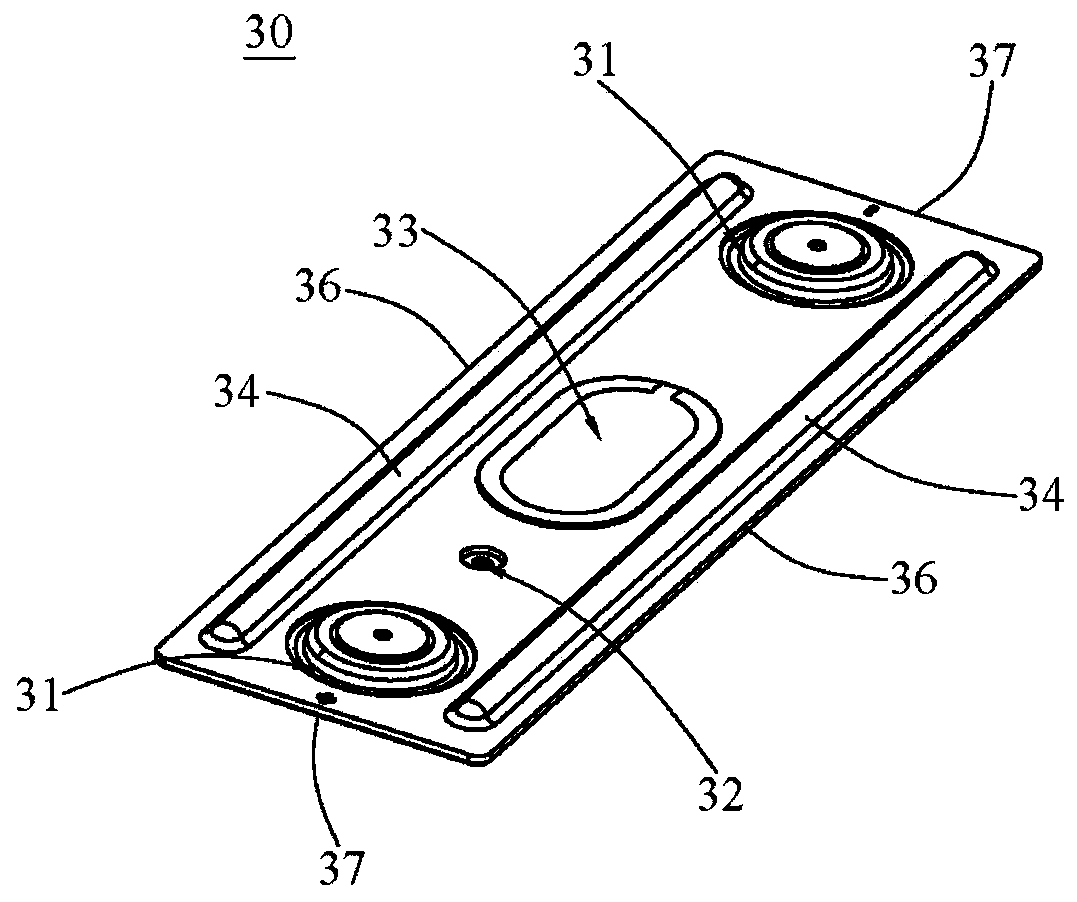
[0028] see image 3 and Figure 4 As shown, the battery top cover reinforcement structure of this embodiment includes a top cover body 30, and the top cove...
no. 2 example
[0032] see Figure 5 and Figure 6 As shown, the difference between this embodiment and the first embodiment lies in the reinforcement structure of the battery top cover. The reinforced structure of the battery top cover in this embodiment includes a top cover body 30, the top cover body 30 is provided with an electrode end hole 31, a liquid injection hole 32, an explosion-proof hole 33 and a first rib 34, wherein the first rib 34 protrudes Extending on the front of the top cover body 30, so that the top cover body 30 has a concave-convex structure, thereby having a better bearing capacity, and the distribution position of the first rib 34 avoids the electrode end hole 31, the liquid injection hole 32, and the explosion-proof hole 33 , to prevent the first rib 34 from obstructing the normal use of the electrode port hole 31 , the liquid injection hole 32 , and the explosion-proof hole 33 .
[0033] Specifically, the first reinforcing rib 34 is block-shaped, and covers the fr...
no. 3 example
[0035] see Figure 7 and Figure 8 As shown, the difference between this embodiment and the first embodiment is that the battery top cover reinforcement structure of this embodiment further includes two second reinforcement ribs 35, and the two second reinforcement ribs 35 protrude from the front of the top cover body 30 respectively. Furthermore, the cooperation with the two first ribs 34 enables the top cover body 30 to have a more complex concave-convex structure, thereby having a better bearing capacity. Same as the first reinforcing rib 34, the distribution position of the two second reinforcing ribs 35 avoids the electrode end hole 31, the liquid injection hole 32, the explosion-proof hole 33, and avoids that the second reinforcing rib 35 hinders the electrode terminal hole 31, the liquid injection hole 32, The normal use of explosion-proof hole 33.
[0036] Specifically, the two second reinforcing ribs 35 respectively extend along the short side 37 of the top cover bo...
PUM
 Abstract
Description
Claims
Application Information
 - R&D
- Intellectual Property
- Life Sciences
- Materials
- Tech Scout
- Unparalleled Data Quality
- Higher Quality Content
- 60% Fewer Hallucinations
Browse by: Latest US Patents, China's latest patents, Technical Efficacy Thesaurus, Application Domain, Technology Topic, Popular Technical Reports.
© 2025 PatSnap. All rights reserved.Legal|Privacy policy|Modern Slavery Act Transparency Statement|Sitemap|About US| Contact US: help@patsnap.com


