Integrated two-stage high-efficiency cyclone separator

A cyclone separator, an integrated technology, applied in the direction of the swirl device, the device whose axial direction of the swirl can be reversed, etc., can solve the problems of high cost, difficult cleaning, easy blockage of blades, etc., and reduce short circuit The effect of flow formation, reduction of separation burden, and reduction of design difficulty

Pending Publication Date: 2020-06-26
上海卓旋化工科技有限公司
View PDF2 Cites 2 Cited by
  • Summary
  • Abstract
  • Description
  • Claims
  • Application Information

AI Technical Summary

Problems solved by technology

But there are following deficiencies: (1) the separator divides the housing cavity into a plurality of end-to-end separation chambers with a partition, and the bottom of each stage of separation chamber is provided with a sewage outlet, that is, the separator has a plurality of sewage outlets , resulting in increased difficulty in the operation of the sewage discharge process and high labor intensity
At the same time, all sewage outlets need to install valves and instruments. The purchase and maintenance costs of valves and instruments will occupy a large proportion of equipment investment, especially in high-pressure working conditions, which will be expensive.
(2) The inlet of each stage of the separation chamber of the separator is provided with spiral blades or guide vane blades to rotate the intake air to achieve centrifugal separation, but such guide vanes are prone to clogging, especially when the gas phase contains viscous When there is a large amount of liquid (such as tar, etc.), the liquid mixed with dust can easily block the guide vane. Once the guide vane in the separator is blocked, it will be very difficult to clean, which is not good for the long-term stable operation of the equipment.

Method used


Image

  • Integrated two-stage high-efficiency cyclone separator
  • Integrated two-stage high-efficiency cyclone separator
  • Integrated two-stage high-efficiency cyclone separator

Examples


Embodiment Construction

[0040] The present invention will be further described below in conjunction with the accompanying drawings and specific embodiments.

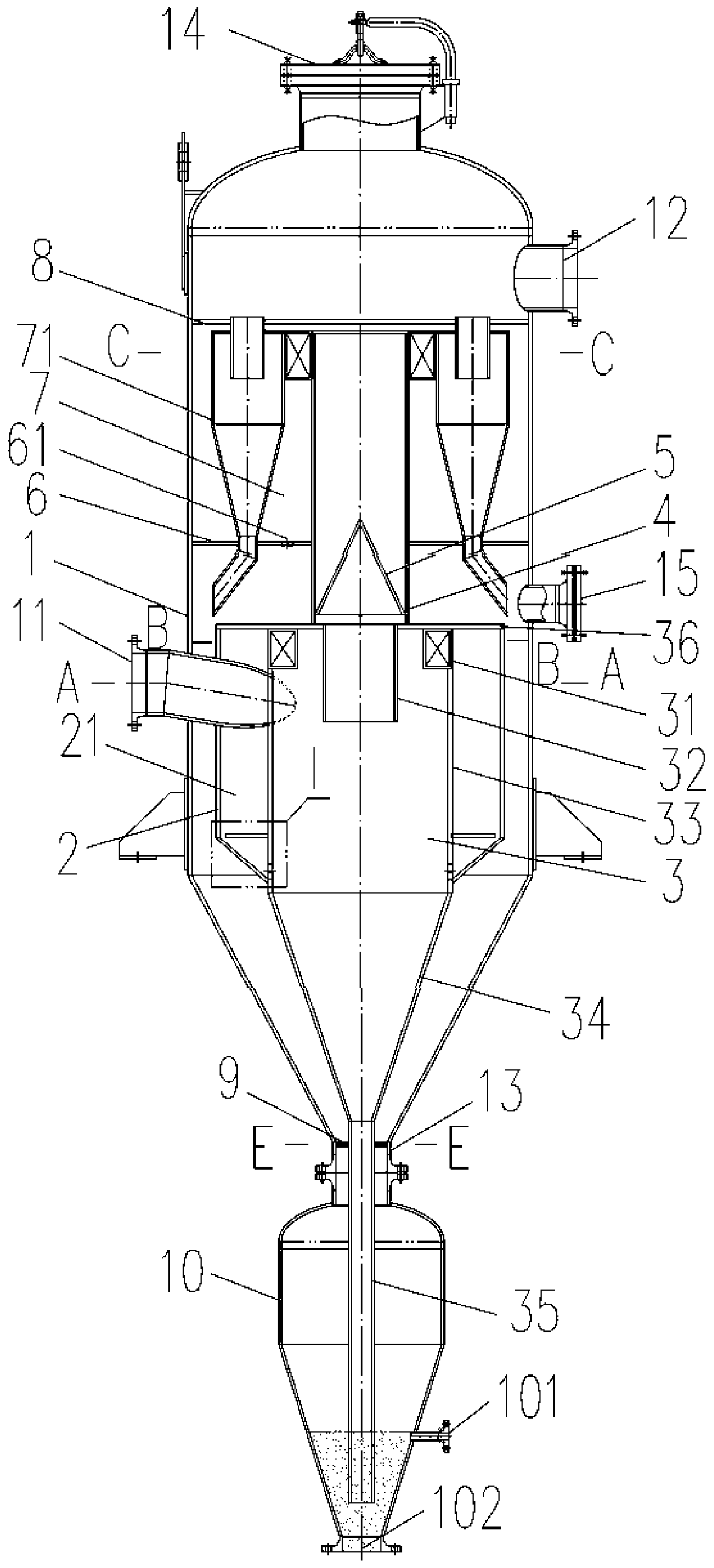
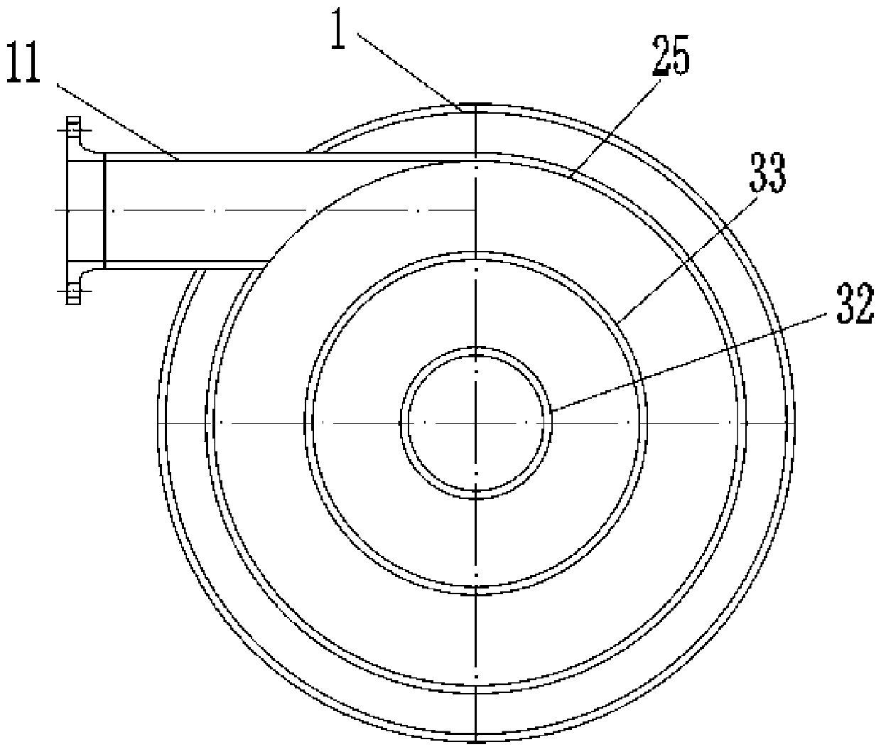
[0041] Please see attached figure 1 , an integrated two-stage high-efficiency cyclone separator, including a housing 1, a gas inlet 11 arranged in the middle of the housing 1, a gas outlet 12 arranged in the upper part of the housing 1, a sewage outlet 13 arranged in the bottom of the housing 1 and The ash hopper 10 connected to the sewage outlet 13; the housing 1 is provided with a pre-separator 2, a first-stage cyclone separator 3, an air riser 4 and a second-stage cyclone separator 7, and the first-stage cyclone separator 3 The upper part is coaxially arranged in the pre-separator 2, the middle part of the outer wall of the first-stage cyclone separator 3 is in sealing connection with the bottom of the pre-separator 2, and the top of the first-stage cyclone separator 3 is in sealing connection with the top of the pre-separator 2, A pre-sepa...


PUM


Abstract

The invention discloses an integrated two-stage high-efficiency cyclone separator. The integrated two-stage high-efficiency cyclone separator comprises a casing (1), a gas inlet (11) formed in the middle of the casing, a gas outlet (12) formed in the upper portion of the casing, a sewage outlet (13) formed in the bottom of the casing, and a dust hopper (10) connected with the sewage outlet; a pre-separator (2), a first-stage cyclone separator (3), a gas rising pipe (4) and a second-stage cyclone separator (7) are arranged in the casing (1), the first-stage cyclone separator is arranged in thepre-separator, and a pre-separation cavity (21) is formed between the pre-separator and the first-stage cyclone separator; and the first-stage cyclone separator penetrates through the sewage outlet and communicates with the dust hopper, the first-stage cyclone separator communicates with the second-stage cyclone separator through the gas rising pipe, and the gas inlet runs through the casing and communicates with the pre-separator. Multi-stage separation is achieved in one separator, and the separator has high separation efficiency and low operation resistance and can operate stably for a longperiod; and impurities collected in each stage of separation are collected together and centralizedly discharged through the same sewage outlet.

Description

technical field [0001] The invention relates to a gas-solid / gas-liquid separation device, in particular to an integrated two-stage high-efficiency cyclone separator. Background technique [0002] As an important gas-solid separation or gas-liquid separation equipment, cyclone separator is widely used in chemical industry, petroleum , environmental protection, food and other industrial fields. Its working principle is that the dust-laden or liquid-laden airflow enters the cyclone separator through the air inlet, and the airflow rotating around its axis is formed in the cyclone separator. Under the action of centrifugal force, the dust or liquid droplets are thrown to the outer wall and discharged downward. The dust outlet is discharged, and the clean gas is discharged through the exhaust pipe in the center. [0003] The following working conditions are often encountered in industrial production: (1) The gas contains a relatively high concentration of impurities, and it is n...

Claims


Application Information

Patent Timeline
Patent Type & Authority Applications(China)
IPC IPC(8): B04C5/24B04C5/30B04C5/00B04C7/00
CPCB04C5/00B04C5/24B04C5/30B04C7/00
Inventor 马双黄晓卫陈启远王景花黄晓军孟祥林黄毅忱张丽
Owner 上海卓旋化工科技有限公司
Why Eureka
Try Eureka