
Semi-solid continuous pulping system

A semi-solid, pulping technology, applied in the field of semi-solid preparation, can solve the problems of excessively large volume of the holding furnace, high cost, low heat preservation precision, etc., and achieve the effects of simple operation, reduction of preparation cost and saving of pulping time.

Pending Publication Date: 2020-06-26
安徽圣尔沃智能装备有限公司
View PDF0 Cites 0 Cited by
  • Summary
  • Abstract
  • Description
  • Claims
  • Application Information

AI Technical Summary

Problems solved by technology

[0005] The present invention mainly provides a semi-solid continuous pulping system, which is used to solve the problem of low heat preservation accuracy due to the large volume of the holding furnace in the preparation process of the existing semi-solid mentioned in the above background technology, and the use of a mobile continuous pulping system. The transportation and transfer of the alloy melt by the rod, the technical problem of high cost

Method used


Image

  • Semi-solid continuous pulping system
  • Semi-solid continuous pulping system
  • Semi-solid continuous pulping system

Examples


Embodiment 1

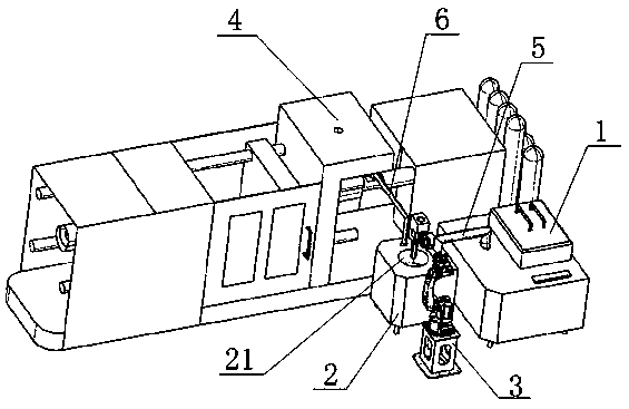
[0027] Refer to attached Figure 1-2 , a semi-solid continuous pulping system, comprising a large quantitative holding furnace 1, a small quantitative holding furnace 2, a stirring device 3 and a die-casting island 4, between the large quantitative holding furnace 1 and the small quantitative holding furnace 2 An extraction pipeline 5, and a delivery pipeline 6 is provided between the small quantitative holding furnace 2 and the die-casting island 4.

[0028] The volume of the large quantitative holding furnace 1 is at least 2 times of the volume of the small quantitative holding furnace 2, the extraction pipeline 5 and the delivery pipeline 6 are provided with quantitative pumps, and the small quantitative holding furnace 2 tops are equipped with There is an opening 21, and the opening 21 is matched with the stirring rod 31 of the stirring device 3, so that the stirring rod 31 is inserted into the small quantitative holding furnace 2, and the stirring rod 31 can continuously ...

Embodiment 2

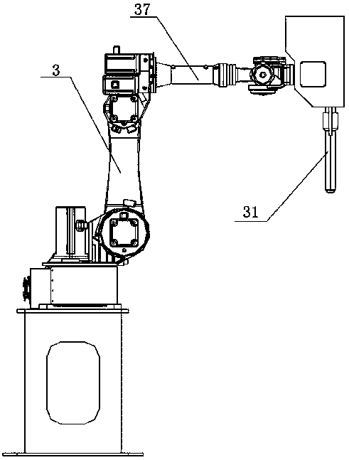
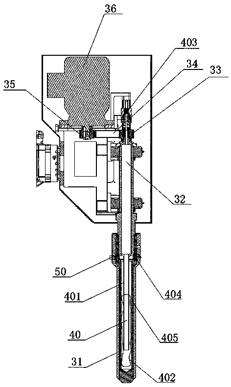
[0032] Refer to attached Figure 2-3 , a stirring device 3 is provided next to the small quantitative holding furnace 2. In the present embodiment, the stirring device 3 used includes a stirring rod 31, and one end of the stirring rod 31 is provided with a rotating shaft 32, and a limiting structure is provided on the rotating shaft 32, so that The rotating shaft 32 can only rotate and cannot move. The end of the rotating shaft 32 is provided with a rotating shaft driven wheel 33. The rotating shaft driven wheel 33 is connected to the rotating shaft driving wheel 35 through the rotating shaft driving link synchronous belt 34. The rotating shaft driving wheel 35 is fixedly connected to the driving motor 36 driving end, a mechanical arm 37 is provided on one side of the stirring rod 31, and the stirring rod 31 is driven by the mechanical arm 37;

[0033] The inside of the stirring rod 31 is provided with a cavity, the cavity is provided with a gas-liquid cooling structure 40, th...


PUM


Abstract

The invention provides a semi-solid continuous pulping system. The semi-solid continuous pulping system comprises a large quantitative holding furnace, a small quantitative holding furnace, a stirringdevice and a die-casting island, wherein an extraction pipeline is arranged between the large quantitative holding furnace and the small quantitative holding furnace; and a conveying pipeline is arranged between the small quantitative holding furnace and the die-casting island. Alloy melt is extracted into the small quantitative holding furnace from the large quantitative holding furnace, the small quantitative holding furnace is used for improving the holding precision, and the pipeline is used for extracting to transfer and transport pulp, so that related mobile transportation equipment such as soup feeding in a conventional pulping process is reduced, the preparation cost is reduced, and the operation is simple; and the semi-solid preparation method can be used for continuously pulping, so that the pulping time is greatly saved, and the production and preparation efficiency is improved; and moreover, the method can be used for extracting relatively pure alloy melt for pulping, so that relatively high-quality die-casting parts are obtained.

Description

technical field [0001] The invention mainly relates to the technical field of semi-solid preparation, in particular to a semi-solid continuous pulping system. Background technique [0002] Semi-solid metal processing is the metal in the solidification process, strong stirring or by controlling the solidification conditions, inhibit the growth of dendrites or break the dendrites generated, forming an equiaxed, uniform, fine primary phase, which is evenly distributed in the liquid phase Suspended semi-solid slurry, this slurry still has good fluidity when the solid phase ratio reaches 60% under the action of external force. [0003] At present, the commonly used method in the preparation of semi-solid slurry is to place the alloy melt in a large-quantity holding furnace, use a crucible or ladle to hold the alloy melt, and move the crucible or ladle by moving the connecting rod. Stirring at the mixing equipment, and then transported to the die-casting equipment for molding, wh...

Claims


Application Information

Patent Timeline
Patent Type & Authority Applications(China)
IPC IPC(8): B22D17/20
CPCB22D17/007B22D17/20
Inventor 蔡东廷李晓丽
Owner 安徽圣尔沃智能装备有限公司
Learn More