

Barrel body hoisting equipment
A technology for hoisting equipment and cylinders, which is applied to the braking device of hoisting equipment, hoisting device, transportation and packaging, etc., can solve the problems of poor ventilation effect at the bottom of the shaft, poor working environment of staff, and low construction efficiency of driving operation. , to achieve the effect of improving the efficiency of construction work and improving the construction work environment
- Summary
- Abstract
- Description
- Claims
- Application Information
AI Technical Summary
Problems solved by technology
Method used
Image

Examples
Embodiment 1
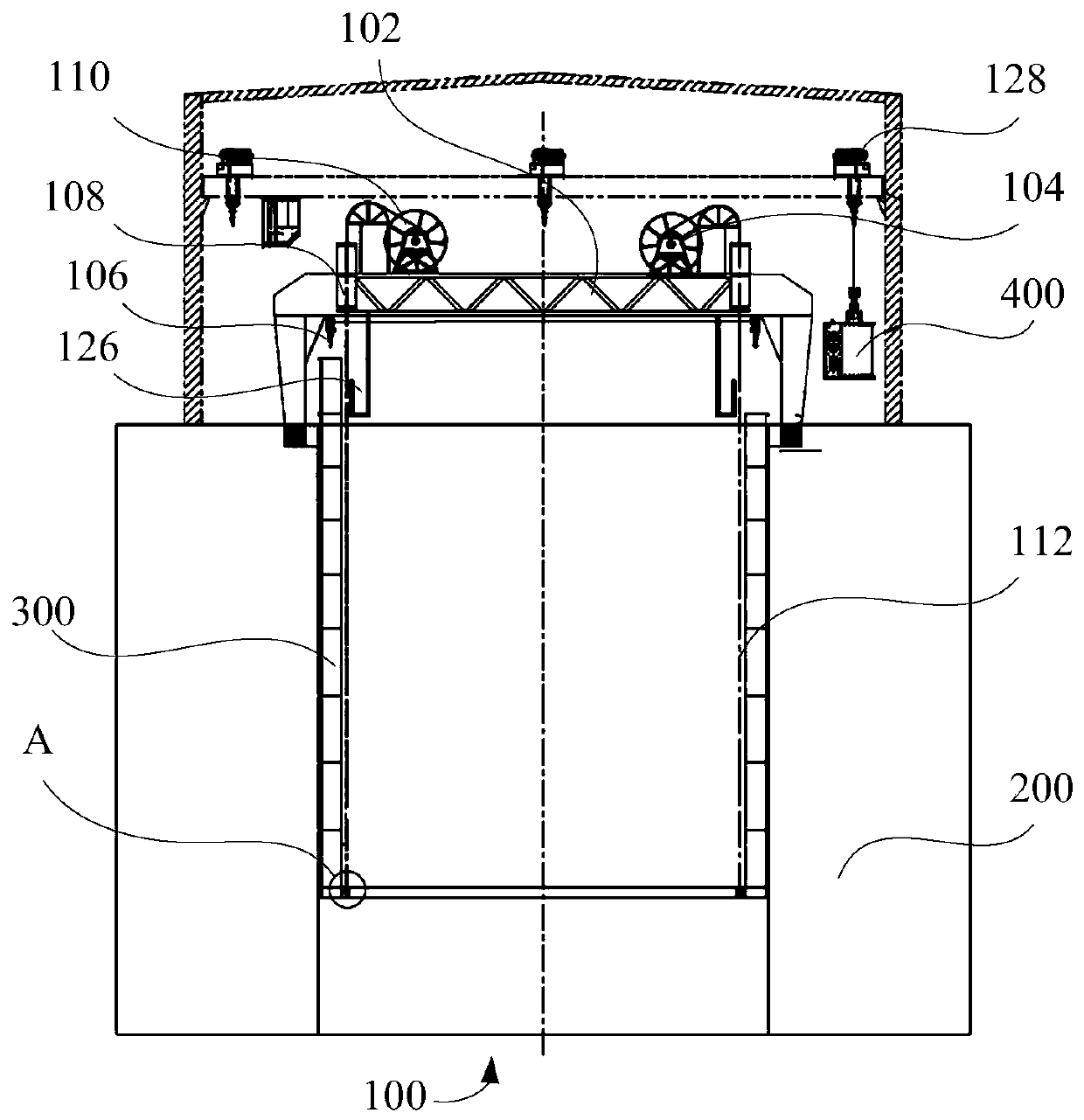
[0046] Such as figure 1 , figure 2 and image 3 As shown, the first embodiment of the present invention proposes a cylinder hoisting device 100 , including: a carrying mechanism 102 , a lifting mechanism 104 and a retrieving mechanism 106 .
[0047] Wherein, the lifting mechanism 104 is arranged on the carrying mechanism 102, and the welded cylinder body 300 is driven up and down by the lifting mechanism 104; the retrieving mechanism 106 is arranged on the carrying mechanism 102, and the material 400 to be welded is placed in the welding area by the retrieving mechanism 106 .
[0048] In this embodiment, the cylinder hoisting device 100 is applied to cylinder welding of a shaft 200 . During the construction process, after the bottommost first layer of cylinder is welded, the welded cylinder 300 can be lifted to the ground by the lifting mechanism 104 , and then the material 400 can be placed in the welding area by the pick-up mechanism 106 . At this time, the staff can we...
Embodiment 2
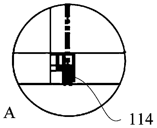
[0059] Such as figure 1 and figure 2 As shown, the second embodiment of the present invention proposes a cylinder hoisting device 100 , including: a carrying mechanism 102 , a lifting mechanism 104 , a retrieving mechanism 106 and a connecting seat 114 .
[0060] Among them, such as figure 2 As shown, the lifting mechanism 104 is arranged on the carrying mechanism 102, the connecting seat 114 is arranged on the bottom of the welded cylinder 300, and the retrieving mechanism 106 is connected with the welded cylinder 300 through the connecting seat 114, thereby realizing the welded cylinder 300 lifting; the material taking mechanism 106 is arranged on the carrying mechanism 102, and the material 400 to be welded is placed in the welding area through the material taking mechanism 106.
[0061] In this embodiment, the rope body 112 is connected to the connection seat 114 to ensure a stable connection between the rope body 112 and the welded cylinder 300 .
[0062] In addition...
Embodiment 3
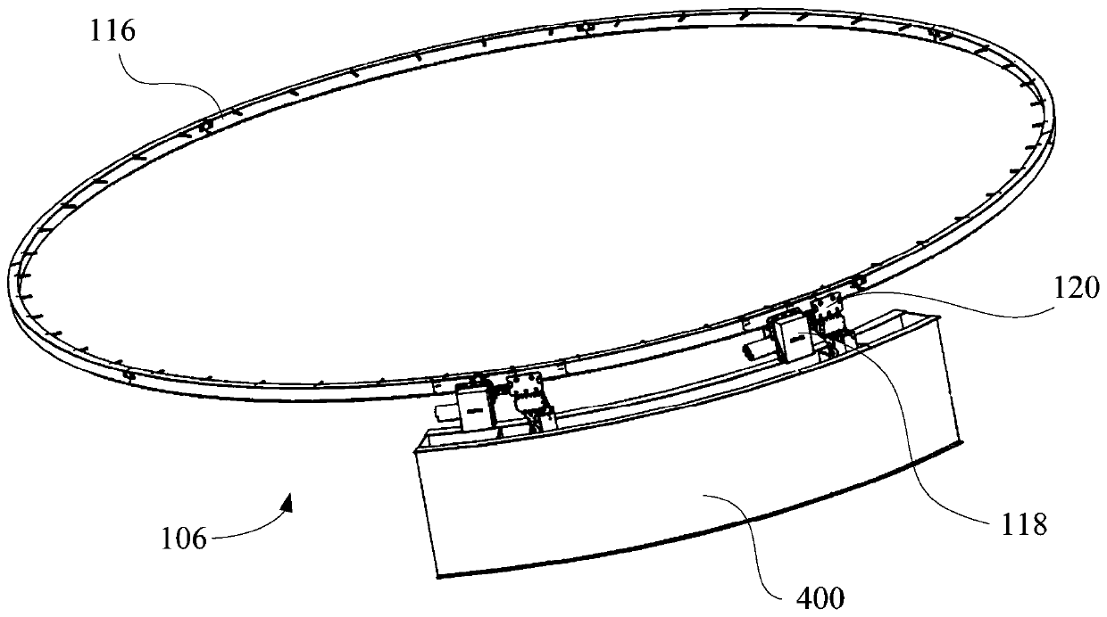
[0065] Such as figure 1 As shown, the third embodiment of the present invention proposes a cylinder hoisting device 100 , which includes: a carrying mechanism 102 , a lifting mechanism 104 , a retrieving mechanism 106 and an annular working platform 126 .
[0066] Wherein, the lifting mechanism 104 is arranged on the carrying mechanism 102, and the welded cylinder body 300 is driven up and down by the lifting mechanism 104; the retrieving mechanism 106 is arranged on the carrying mechanism 102, and the material 400 to be welded is placed in the welding area by the retrieving mechanism 106 ; The ring-shaped working platform 126 is set on the carrying mechanism 102, and is used for the positioning of the material during the welding process.
[0067] Specifically, an annular working platform 126 is provided on the supporting mechanism 102, and the annular working platform 126 is concentrically arranged with the wellhead of the shaft 200. The outer diameter of the annular working ...
PUM
 Abstract
Description
Claims
Application Information