
An oil field downhole fracturing material feeder

A technology for oil field wells and materials, applied in drilling equipment, wellbore/well components, drill pipes, etc., can solve the problems of insufficient gas pressure, large feeding amount, large water consumption, etc., achieve free and fast connection, reduce load, The effect of avoiding damage

Active Publication Date: 2022-02-01
北京瑞丰宇胜科技有限公司
View PDF0 Cites 0 Cited by
  • Summary
  • Abstract
  • Description
  • Claims
  • Application Information

AI Technical Summary

Problems solved by technology

After actual use, it is found that the problems of this device are: a. The air leakage of the closed air feeder is serious after eight hours of operation; b. Due to the large amount of feed, the gas pressure is sufficient, and the wind speed cannot meet the requirements for use, resulting in the material being trapped in the tube. c. Since this kind of cement proppant is tiny particles with light specific gravity, and the particles are not hydrophilic, when it is sent to the vehicle-mounted fracturing mixing tank by the wind, it will be scattered by the wind, which is not conducive to uniform mixing; d. It cannot be quantified delivery
[0004] High-pressure jet material conveying equipment adopts jet flow technology, and uses a certain proportion of water to form high-pressure conveying. Although this method is good, but the water consumption is too large, the equipment is large in size, and transportation is difficult; the conveying pipeline is long and difficult to construct in winter
[0005] To sum up, neither of the above two existing devices can meet the requirements of material delivery well, so inventing a new fracturing material delivery device has become a technical problem to be solved urgently by those skilled in the art

Method used


Image

  • An oil field downhole fracturing material feeder
  • An oil field downhole fracturing material feeder
  • An oil field downhole fracturing material feeder

Examples


Embodiment Construction

[0022] In order to make the technical problems, technical solutions and beneficial effects to be solved by the present invention clearer, the present invention will be further described in detail below in conjunction with the accompanying drawings and embodiments.

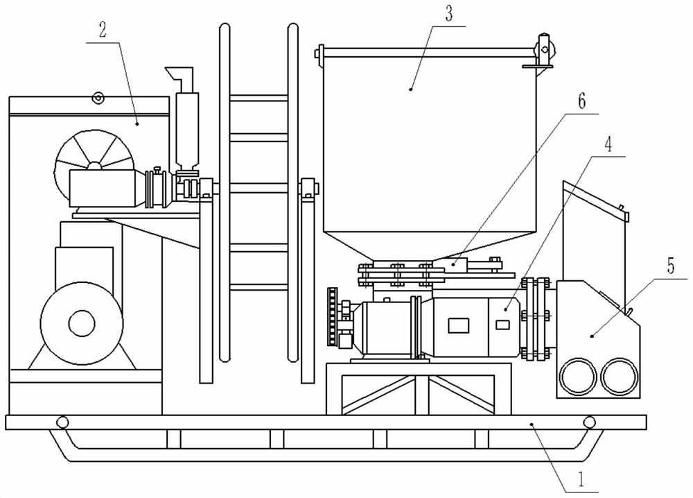
[0023] Such as figure 1 As shown, this embodiment includes a skid-mounted chassis 1 on which a generator 2 , a material box 3 , a quantitative material control device 4 and a material converter 5 are installed. The generator 2 is used to supply power to the electrical components. The material box 3 is fixedly installed above the quantitative material control device 4, and the two are connected by an electric gate valve 6.

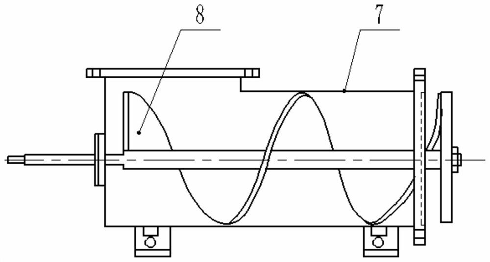
[0024] Such as figure 2 Said, the quantitative material control device 4 includes a box body 7, a frequency converter, a variable frequency motor and a screw blade 8, the two ends of the box body 7 are respectively provided with a material inlet and a discharge port, and the screw blade 8 is...


PUM


Abstract

The invention belongs to the technical field of oilfield fracturing equipment, and in particular relates to an oilfield downhole fracturing material feeding machine, which includes a skid-mounted chassis, and the chassis is equipped with a generator, a material box, a quantitative material control device and a material converter ; The quantitative material control device includes a box body, a frequency converter, a variable frequency motor and a screw blade, and the two ends of the box body are respectively provided with a material inlet and a material outlet, and the described screw blade is installed in the box body. The variable frequency motor drives the helical blades to rotate, so as to push the material from the inlet of the box to the outlet. The feed port is connected to the material converter, and the material converter includes a converter box, a steel wire hose, a coil spring and a drive motor, and the steel wire hose is divided into at least two sections, and the gap between two adjacent sections is Connection via spring centralizers.

Description

technical field [0001] The invention belongs to the technical field of oilfield fracturing equipment, and in particular relates to an oilfield downhole fracturing material feeder. Background technique [0002] With the continuous development of petroleum industry technology, a new type of cement proppant is used for downhole fracturing in oil fields to keep the cracks open after fracturing. The proppant is made of tiny particles made of polypropylene, with a particle diameter of 80 mesh. Left and right, light in specific gravity. During downhole fracturing, the demand for proppant varies from well to well, ranging from 0.2 to 2.5 cubic meters per minute. The actual production must be delivered quantitatively according to the needs of each well. In addition, due to the limited space and site requirements, the transportation of materials must be long-distance transportation, requiring a transportation distance of more than 10 meters. In addition, the location between the mate...

Claims


Application Information

Patent Timeline
Patent Type & Authority Patents(China)
IPC IPC(8): E21B43/26E21B17/10
CPCE21B43/26E21B17/1078
Inventor 孙显清
Owner 北京瑞丰宇胜科技有限公司
Learn More