A sealing device for high-speed rotary impeller machinery

A technology of sealing device and impeller machinery, which is applied in the direction of mechanical equipment, engine components, machines/engines, etc., can solve the problems of increased leakage, large difference in sealing performance, enhanced axial vibration of the rotating shaft, etc. Oblique and axial linearity are good, and the effect of axial vibration compensation

Active Publication Date: 2022-05-27
XIHUA UNIV
View PDF5 Cites 0 Cited by
  • Summary
  • Abstract
  • Description
  • Claims
  • Application Information

AI Technical Summary

Problems solved by technology

[0004] 1. The sealing effect is unstable, the leakage increases significantly when the shaft rotates at high speed, and the axial vibration of the rotating shaft increases, which will affect the stiffness stability of the sealed air film;
[0005] 2. Poor adaptability and versatility. When the impeller machinery is in different working conditions, the medium pressure in the impeller machinery changes or the rotating shaft is at different speeds, and it is impossible to control and adjust the sealing performance of the sealing device in real time, resulting in the impeller machinery. Under different working conditions, the sealing performance is quite different;
[0006] 3. When the impeller machinery starts and stops, the speed is relatively low, and the sealing dynamic pressure air film cannot be produced in time between the moving ring and the static ring, resulting in leakage; and during the normal high-speed operation of the impeller machinery, the gap between the moving ring and the static ring Insufficient rigidity of sealing dynamic pressure gas film, poor stability of gas film rigidity, affecting the sealing effect

Method used


Image

  • A sealing device for high-speed rotary impeller machinery
  • A sealing device for high-speed rotary impeller machinery
  • A sealing device for high-speed rotary impeller machinery

Examples


Embodiment Construction

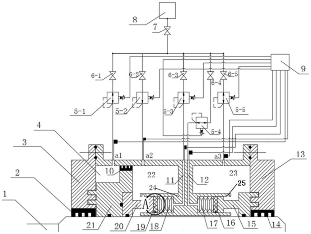
[0027]The present invention provides a sealing device for high-speed rotating impeller machinery. The sealing device for high-speed rotating impeller machinery is a multi-stage combined sealing structure formed by a double-end hydrodynamic mechanical seal and a labyrinth rotary seal; the sealing device has a sealing control system, and the sealing control system is the The sealing device provides a certain pressure of sealing protective gas, and monitors and controls the working conditions of the sealing protective gas and the sealing device in real time.

[0028] The sealing device has a rotating shaft 1, a left end cover 3 and a right end cover 13, and two ends are respectively connected with the left end cover 3 and the right end cover 13. The circumferential shell is fixedly connected; the left end cover 3 and the right end cover 13 are respectively provided with a first labyrinth seal The device 2 and the second labyrinth seal device 14, the first labyrinth seal device 2 ...


PUM


Abstract

The present invention proposes a sealing device for high-speed rotating impeller machinery. The sealing device is a multi-stage combined sealing structure formed by a double-face hydrodynamic mechanical seal and a labyrinth rotary seal; it has a sealing control system that provides A sealing shielding gas with a certain viscosity and pressure, and real-time monitoring and control of the working conditions of the sealing shielding gas and the sealing device; the dynamic pressure spring is used to provide pre-tightening force for the end faces of the sealing dynamic ring and the static ring; the sealing dynamic ring from There is an inclined surface less than 10 degrees from the outer circumference of the ring end face to the middle part of the ring radial direction of the ring end face. The sealing device can quickly generate labyrinth sealing channel pressure and end face dynamic pressure air film at low speed, and the end face dynamic pressure air film has strong rigidity, good stability, and excellent and stable sealing performance.

Description

technical field [0001] The present application relates to the field of seals for impeller machinery, in particular to a multi-stage combined sealing device used for high-speed rotating precision impeller machinery rotary shaft seals. Background technique [0002] The sealing method of the rotating shaft of the existing turbomachinery is usually a non-contact hydrodynamic mechanical seal. The non-contact fluid dynamic pressure mechanical seal is to open different forms of dynamic pressure grooves on the end faces of the sealing dynamic ring and the static ring. When the sealing dynamic ring and the static ring rotate relative to each other, a dynamic pressure effect is generated, so that the sealing end faces are opened to generate sealing gas. The non-contact sealing of the end faces of the sealing dynamic ring and the static ring is realized by using the sealing gas film. It reduces the friction loss between the seal end faces and prolongs the service life of the seal. In ...

Claims


Application Information

Patent Timeline
Patent Type & Authority Patents(China)
IPC IPC(8): F01D11/00F01D11/02
CPCF01D11/003F01D11/02
Inventor 史广泰王彬鑫刘宗库文海罡
Owner XIHUA UNIV
Why Eureka
Try Eureka