
Microscopic differential reflectance spectroscopy measurement system and method for measuring thickness of nano film

A differential reflection and spectral measurement technology, applied in measurement devices, optical devices, instruments, etc., can solve the problem of not having the ability to measure differential reflection signals in microscopic or micro-area, and achieve reduction of measurement errors, simple optical path structure, and expansion. good effect

Active Publication Date: 2021-08-13
量衡技术(天津)有限公司
View PDF0 Cites 0 Cited by
  • Summary
  • Abstract
  • Description
  • Claims
  • Application Information

AI Technical Summary

Problems solved by technology

[0003] The current differential reflectance optical measurement system is mainly based on spectral signal measurement, without a reference optical path, and needs to perform two measurements on the substrate, the combination of the substrate and the nano-film, resulting in a very obvious drift of the measurement signal with the light intensity, and it does not have Microscopic or micro-area differential reflection signal measurement capability

Method used


Image

  • Microscopic differential reflectance spectroscopy measurement system and method for measuring thickness of nano film
  • Microscopic differential reflectance spectroscopy measurement system and method for measuring thickness of nano film
  • Microscopic differential reflectance spectroscopy measurement system and method for measuring thickness of nano film

Examples


Embodiment Construction

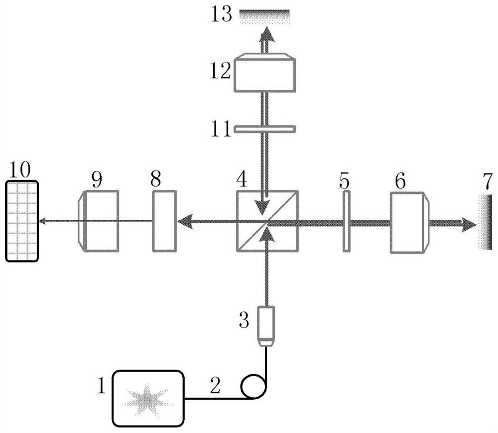
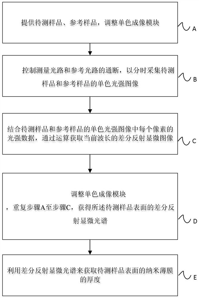
[0032] The invention provides a microscopic differential reflection spectrum measurement system and method for measuring the thickness of a nanometer film. The light output by the light source is respectively entered into the measurement optical path and the reference optical path through a beam splitter, and the samples to be measured and the reference samples are measured respectively. The real-time measurement of light intensity drift can be realized, the measurement error can be effectively reduced, and the microscopic spectrum measurement of the sample to be tested and the reference sample can be realized through the design of the measurement optical path and the reference optical path.

[0033] In order to make the object, technical solution and advantages of the present invention clearer, the present invention will be described in further detail below in conjunction with specific embodiments and with reference to the accompanying drawings.

[0034] Certain embodiments of...


PUM

PropertyMeasurementUnit
diameteraaaaaaaaaa
diameteraaaaaaaaaa

Abstract

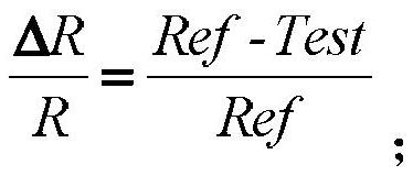
A microscopic differential reflectance spectroscopy measurement system and method for measuring the thickness of a nanometer film. The system includes a light source module, a beam splitter, a measurement optical path, a reference optical path, a monochromatic imaging module, and a data processing module; the light source module outputs non-polarized polychromatic Parallel light beams form two illumination beams through the beam splitter; one illumination beam enters the measurement optical path, converges and enters the sample to be measured; the reflected light beam on the surface of the sample to be measured passes through the measurement optical path and the beam splitter, and is first detected by the monochromatic imaging module. Optical microscopic image acquisition; another illumination beam enters the reference optical path, converges and incidents on the reference sample; the reflected light beam of the reference sample passes through the reference optical path and beam splitter, and the second optical microscopic image acquisition is performed by the monochromatic imaging module; data processing module The first and second optical microscopic images corresponding to different wavelengths are processed to obtain a differential reflection microscopic spectrum. The invention realizes real-time measurement of light intensity drift, and effectively suppresses common-mode errors based on differential optical measurement.

Description

technical field [0001] The invention relates to the technical field of optical in-situ characterization of nanometer film thickness and the technical field of nanostructure testing, in particular to a microscopic differential reflection spectrum measurement system and method for measuring the thickness of nanometer film. Background technique [0002] The in-situ measurement of nano-film thickness and the optical characterization and testing methods of nano-structure play an important role in the research and improvement of its technology. Among them, the differential reflection optical technology measures the reflectivity change caused by the surface reflection of the nano-film, and uses the optical model to study and analyze the film thickness and shape. [0003] The current differential reflectance optical measurement system is mainly based on spectral signal measurement, without a reference optical path, and needs to perform two measurements on the substrate, the combinat...

Claims


Application Information

Patent Timeline
Patent Type & Authority Patents(China)
IPC IPC(8): G01B11/06
CPCG01B11/06
Inventor 霍树春胡春光王浩胡晓东胡小唐
Owner 量衡技术(天津)有限公司
Learn More