Safety alarm intelligent processing system capable of remotely stopping crimes
A security alarm and processing system technology, applied in the direction of alarms, electrical transmission signal systems, instruments, etc., can solve the problems of not being able to stop losses in time, not being able to disperse and refusing the defense methods of intruders, etc., to reduce economic losses. , Increase the protection function, the effect of protecting important assets
- Summary
- Abstract
- Description
- Claims
- Application Information
AI Technical Summary
Problems solved by technology
Method used
Image
Examples
Embodiment 1
[0036] see figure 1 , a security alarm intelligent processing system capable of remotely stopping crimes, comprising: an alarm host, a monitoring module, and a defense module; the alarm host is internally provided with a control module, a communication module, and an alarm module; the control module is connected to the monitoring module respectively , defense module communication module connection;
[0037] The monitoring module includes an infrared sensor and a vibration sensor; the infrared sensor and the vibration sensor can detect the number of intruders, and transmit the information on the number of intruders to the control module; the control module determines that there are personnel activities at the monitoring position, Then the control module sends an alarm signal to the alarm module;
[0038]The monitoring module also includes a camera 4 and an alarm positioning fence. The alarm positioning fence is respectively provided with a fence 1 and a reflector 2 at both end...
Embodiment 2
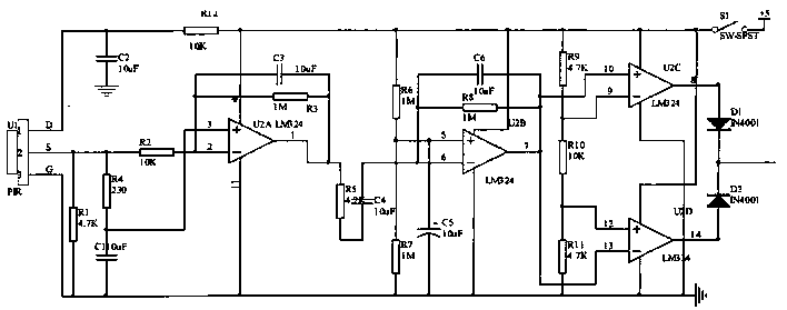
[0045] Such as figure 2 As shown, the monitoring module also includes LM324 infrared sensing signal processor, pyroelectric infrared sensor and peripheral components; The infrared sensor senses the analog signal, and then the infrared sensor signal processor converts the analog signal into a digital signal, and sends the detection result to the control module. The control module controls the wireless transmitting device to send a signal. After the wireless receiving device receives the transmitting signal, it executes Commands to launch tear gas, smoke bombs, rubber guns or gun net attacks; remotely drive intruders, effectively reducing economic losses.
[0046] Schematic diagram of the LM324 pyroelectric infrared detection circuit. The pyroelectric infrared sensor D terminal is connected to the power supply, the G terminal is grounded, and the S terminal is connected to the output. The tiny output of the pyroelectric infrared sensor is first low-pass filtered, and then coupl...
Embodiment 3
[0049] On the basis of embodiment one and two, as Figure 3-4 As shown, the wireless transmission circuit adopts PT2262 and 315MHz transmitter circuit. During the working process of the wireless transmission circuit, first connect the 14 pins to the ground and start the encoding terminal. When the monitoring module outputs an effective high level, the transistor Q2 is turned on, and the relay switch K2 Pull in the high level to turn on the power supply, and the data terminal of the D0 pin inputs a high level, the D0 pin is pulled down internally, and the code is sent out, and then the transmitter circuit is started by outputting a high level signal through the 17-pin code, and the code is sent out through the 315MHz transmitter circuit ;The wireless receiving circuit is output by pin 1 of LM358, and the output is connected to pin 14 of the decoding chip PT2272, so that the address code is consistent with PT2262. After decoding, the LED connected to pin 17 can judge whether the ...
PUM
 Abstract
Description
Claims
Application Information
 - R&D
- Intellectual Property
- Life Sciences
- Materials
- Tech Scout
- Unparalleled Data Quality
- Higher Quality Content
- 60% Fewer Hallucinations
Browse by: Latest US Patents, China's latest patents, Technical Efficacy Thesaurus, Application Domain, Technology Topic, Popular Technical Reports.
© 2025 PatSnap. All rights reserved.Legal|Privacy policy|Modern Slavery Act Transparency Statement|Sitemap|About US| Contact US: help@patsnap.com


