
Civil aircraft keel beam structure for improving comprehensive performance of structure

A technology of structural synthesis and beam structure, which is applied to the fuselage, aircraft parts, fuselage frame, etc., can solve the problems of increased processing and assembly steps, long edge force transmission routes, and large deformation of the upper wall plate, etc., to achieve improved The effect of structural comprehensive performance, increasing area and reducing overall deformation

Inactive Publication Date: 2020-06-30
湖北鸿翼航空科技有限公司
View PDF0 Cites 0 Cited by
  • Summary
  • Abstract
  • Description
  • Claims
  • Application Information

AI Technical Summary

Problems solved by technology

[0005] On the whole, the existing technology mainly has the following defects: The main disadvantages of the keel beams of Boeing Company are that the long flanges have a long force transmission route and are not easy to maintain, and the long flanges need to be replaced as a whole when they need to be replaced, which greatly increases the cost
However, the keel beam of Airbus does not directly support the central wing box, and additional processing parts are required to ensure the connection between the central wing box and the keel beam, which increases the processing and assembly steps and increases the cost.
In addition, the keel beams of the two companies do not support the upper wall in the landing gear compartment. For wide-body passenger aircraft, the lateral span of the landing gear compartment is larger than that of narrow-body passenger aircraft. The lack of support on the upper wall is affected by passengers and Large deformation after equipment pressure

Method used


Image

  • Civil aircraft keel beam structure for improving comprehensive performance of structure
  • Civil aircraft keel beam structure for improving comprehensive performance of structure
  • Civil aircraft keel beam structure for improving comprehensive performance of structure

Examples


Embodiment Construction

[0026] The technical scheme of a civil aircraft keel beam structure for improving the comprehensive performance of the structure provided by the present invention will be further described below in conjunction with the accompanying drawings, so that those skilled in the art can better understand the present invention and implement it.

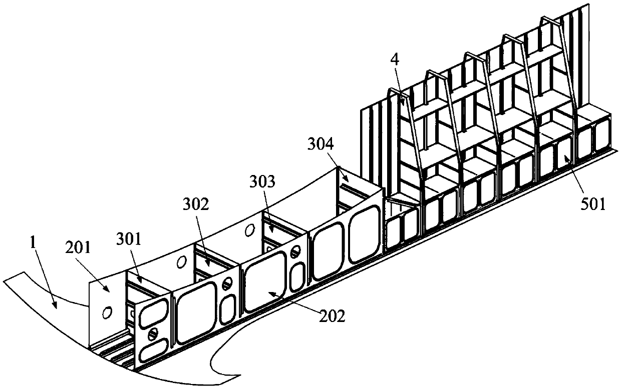
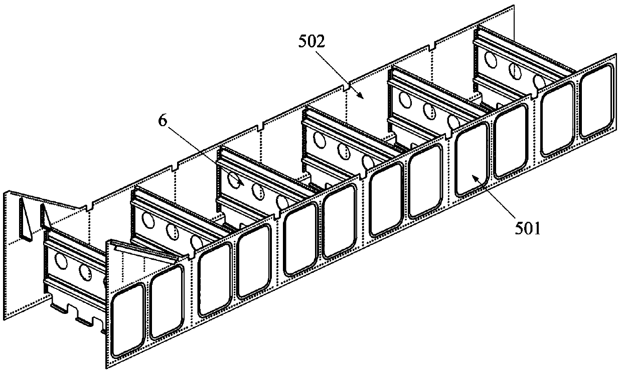
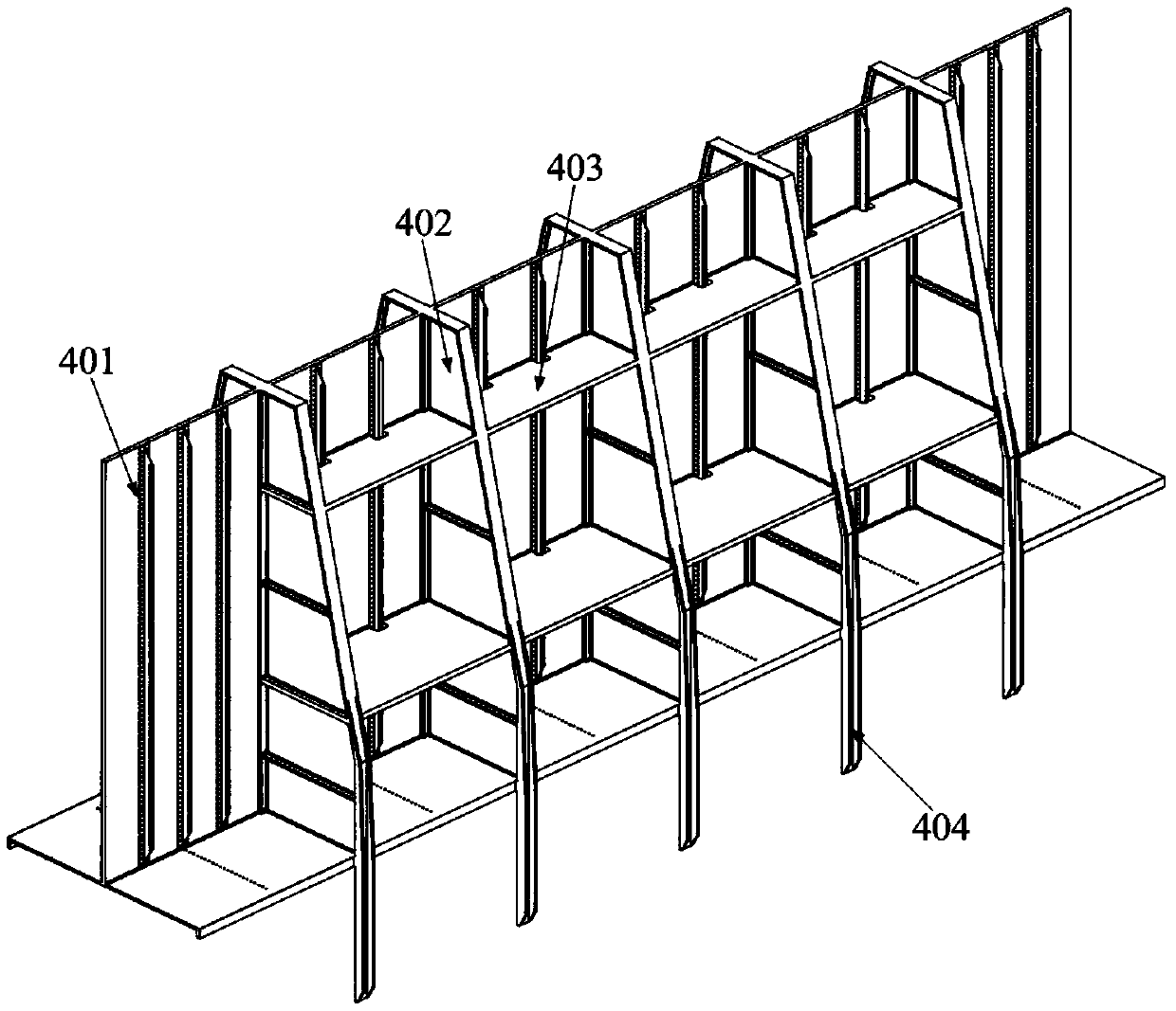
[0027] see figure 1 , figure 2 , image 3 , a civil aircraft keel beam structure that improves the comprehensive performance of the structure, and is an integral box-section structure. Located inside the middle fuselage, it includes the central wing box section structure arranged at the front end, the main landing gear box section structure arranged at the rear end, and the "H" type support frame 4 arranged above the main landing gear box section structure. The structure of the central wing box section is composed of the reinforced bottom plate 1, the left front side plate 201, the right front side plate 202, the ribs 301 of the No. 1 machin...


PUM


Abstract

The invention provides a civil aircraft keel beam structure capable of improving the comprehensive performance of the structure. The civil aircraft keel beam structure arranged in the middle fuselagecomprises a central wing box section structure arranged at the front end, a main landing gear cabin box section structure arranged at the rear end and an H-shaped supporting frame arranged above the main undercarriage cabin box section structure; and the H-shaped supporting frame supports a main landing gear cabin and transmits distributed loads. The undercarriage cabin has a double-closed-chamberstructure formed by an original single-closed-chamber structure, the torsional rigidity of the middle fuselage is improved, deformation at the position is reduced, the area of the undercarriage cabinis increased, and installation space is provided for multiple devices in the undercarriage cabin. The central wing box and the undercarriage cabin section are supported in the normal flight process of an airplane; when the airplane falls and collides, the keel beam makes contact with the ground the structure can be damaged in time, energy generated by collision can be absorbed, so that the overload borne by the body of a passenger is reduced; and thus the survival probability of the passenger in an airplane accident is increased, and the falling adaptability of the airplane is improved.

Description

technical field [0001] The invention relates to a keel beam structure of a civil aircraft, in particular to a keel beam structure of a civil aircraft for improving the comprehensive performance of the structure, and belongs to the technical field of civil aviation structures. Background technique [0002] In the civil aircraft structure, the keel beam is one of the important components of the fuselage structure, just like the "spine" of the aircraft, and its structural integrity directly affects the flight safety of the aircraft. Since the wings are docked through the central wing box in the middle fuselage section, the main landing gear is retracted in the middle fuselage, resulting in a large opening at the lower part of the middle fuselage. The loads of the front and rear fuselages must be transmitted through the keel beam, which is one of the most stressed structural elements in the fuselage structure. It mainly bears the longitudinal axial force caused by the longitudin...

Claims


Application Information

Patent Timeline
IPC IPC(8): B64C1/06
CPCB64C1/064
Inventor 田云彭超
Owner 湖北鸿翼航空科技有限公司
Learn More