Catadioptric panoramic imaging system and imaging method thereof

A catadioptric panorama and imaging system technology, applied in catadioptric panorama imaging system and its imaging field, can solve the problems of high processing cost, large number of lenses, complicated installation, etc., and achieves low light energy loss, good image surface uniformity, good flexibility

Inactive Publication Date: 2020-06-30
PUTIAN UNIV
View PDF9 Cites 2 Cited by
  • Summary
  • Abstract
  • Description
  • Claims
  • Application Information

AI Technical Summary

Problems solved by technology

However, the fisheye lens optical system uses a large number of lenses, resulting in high processing costs, complicated installation, and large aberrations.

Method used


Image

  • Catadioptric panoramic imaging system and imaging method thereof
  • Catadioptric panoramic imaging system and imaging method thereof
  • Catadioptric panoramic imaging system and imaging method thereof

Examples


Embodiment Construction

[0029] The present invention will be further described below in conjunction with the accompanying drawings and specific embodiments.

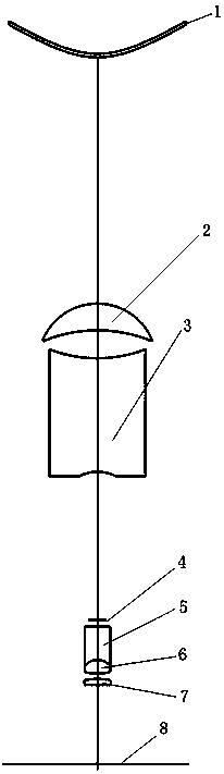
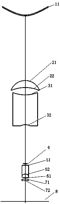
[0030] Such as figure 1 As shown, a catadioptric panoramic imaging system, the optical system is sequentially provided with a front group A, a diaphragm, and a rear group B along the light from the object side to the image side, and the front group A includes mirrors A- 1. Crescent-shaped lens A-2, biconcave lens A-3, the rear group B includes biconcave lens B-1, biconvex lens B-2, and biconvex lens B-3 arranged in sequence, and the biconcave lens B-1 and The biconvex lens B-2 is closely bonded into a cemented group, and the reflector A-1, the crescent lens A-2, the biconcave lens A-3, the biconvex lens B-1, the biconvex lens B-2, and the biconvex lens B-3 are each block Both optical surfaces of the lens adopt spherical design, and the diaphragm adopts an aperture diaphragm.

[0031] In this embodiment, the mirror A-1, the crescent lens A-2, ...


PUM


Abstract

The invention relates to a catadioptric panoramic imaging system and an imaging method thereof. The optical system is sequentially provided with a front group A, a diaphragm and a rear group B from anobject side to an image side along light. The front group A comprises a reflector A-1, a crescent lens A-2 and a biconcave lens A-3 which are arranged in sequence, the rear group B comprises a biconcave lens B-1, a biconvex lens B-2 and a biconvex lens B-3 which are arranged in sequence, and the biconcave lens B-1 and the biconvex lens B-2 are connected in a sealed mode to form a gluing group. The optical system is simple in structure, reasonable in design, wide in view field range, good in image surface uniformity, good in imaging quality, and convenient to process and install.

Description

technical field [0001] The invention relates to a catadioptric panoramic imaging system and an imaging method thereof. Background technique [0002] In recent years, due to the development of application fields such as machine vision, virtual reality, robot navigation, and security monitoring, people have put forward requirements for real-time imaging of scenes in all directions in space, and at the same time, higher requirements have been put forward for the resolution of collected images. [0003] At present, the fisheye lens optical imaging system is often used to solve people's requirements for real-time imaging of scenes in all directions in space. This type of optical system compresses the field of view angle by applying a number of negative meniscus lenses in front of the system for refraction, so as to achieve a large The effect of field of view shooting. However, the number of lenses used in the fisheye lens optical system is large, resulting in high processing cos...

Claims


Application Information

Patent Timeline
Patent Type & Authority Applications(China)
IPC IPC(8): G02B17/08
CPCG02B17/08
Inventor 曹一青陈雪娇沈志娟蔡丽晗陈志亮
Owner PUTIAN UNIV
Why Eureka
Try Eureka