Double-frequency PCB helical antenna

A helical antenna and helical technology, which is applied in the direction of antenna, antenna grounding device, antenna grounding switch structure connection, etc., can solve the problem that the PCB antenna cannot work in dual-frequency mode, and achieve the advantages of increasing capacitance, improving matching, and reducing size Effect

Active Publication Date: 2020-06-30
CIG SHANGHAI
View PDF10 Cites 1 Cited by
  • Summary
  • Abstract
  • Description
  • Claims
  • Application Information

AI Technical Summary

Problems solved by technology

[0004] The technical problem to be solved by the present invention is to provide a dual-frequency PCB helical ant

Method used


Image

  • Double-frequency PCB helical antenna
  • Double-frequency PCB helical antenna
  • Double-frequency PCB helical antenna

Examples


Embodiment Construction

[0024] The present invention is further illustrated below by means of examples, but the present invention is not limited to the scope of the examples.

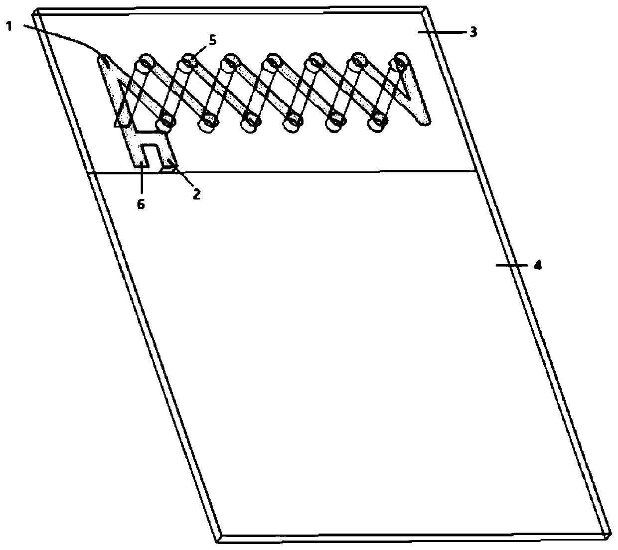
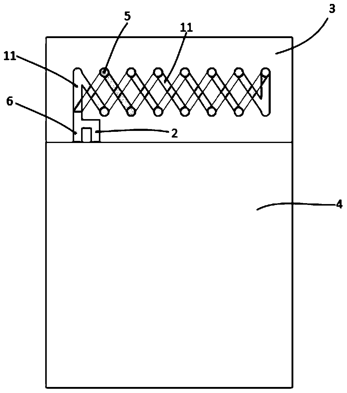
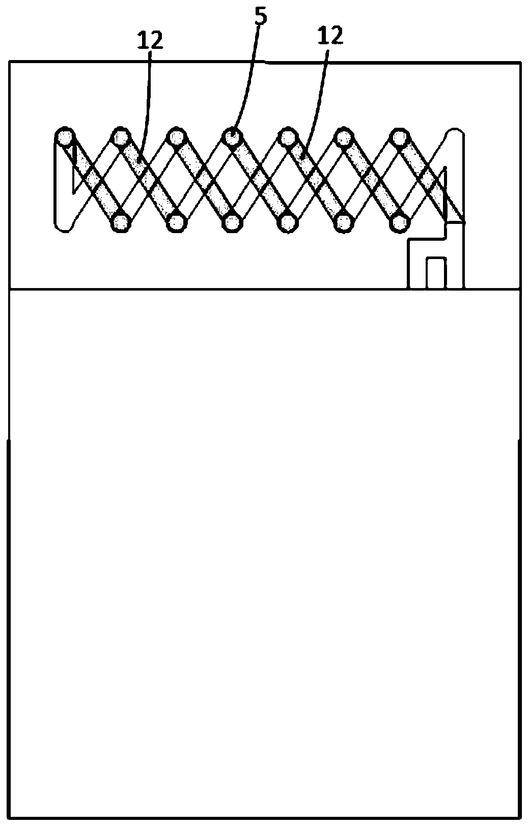
[0025] refer to Figure 1-Figure 3 , a dual-frequency PCB helical antenna according to an embodiment of the present invention, which includes a PCB dielectric substrate 3, a helical antenna 1, a matching short-circuit microstrip line 2 and a metal ground 4, wherein the helical antenna 1, the matching short-circuit microstrip line 2 and the metal ground 4 are both arranged on the PCB dielectric substrate 3, one end of the matching short-circuit microstrip line 2 is connected to the metal ground 4, and the other end of the matching short-circuit microstrip line 2 is connected to the helical antenna 1 , the helical antenna 1 includes a front microstrip line 11 arranged on the front side of the PCB dielectric substrate 3 and a back microstrip line 12 arranged on the back side of the PCB dielectric substrate 3, the front microstrip...


PUM

PropertyMeasurementUnit
Widthaaaaaaaaaa

Abstract

The invention discloses a double-frequency PCB (Printed Circuit Board) helical antenna. The double-frequency PCB helical antenna comprises a PCB dielectric substrate, a helical antenna, a matching short-circuit microstrip line and a metal ground, wherein the helical antenna, the matching short-circuit microstrip line and the metal ground are all arranged on the PCB dielectric substrate; one end ofthe matched short-circuit microstrip line is connected with the metal ground; the other end of the matched short-circuit microstrip line is connected with the helical antenna; the helical antenna comprises a front microstrip line arranged on the front surface of the PCB dielectric substrate and a back microstrip line arranged on the back surface of the PCB dielectric substrate, and the front microstrip line and the back microstrip line are connected through a metal via hole located on the PCB dielectric substrate. Compared with an existing dual-band antenna, the double-frequency PCB helical antenna is small in size, low in cost, high in efficiency, easy to integrate and easy and convenient to machine.

Description

technical field [0001] The invention relates to a PCB antenna. Background technique [0002] An antenna is an energy converter that converts the guided wave propagating on the transmission line into an electromagnetic wave propagating in an unbounded medium, or vice versa. The lower the frequency, the longer the wavelength and the longer the antenna. Generally, antennas are reversible, that is, the same antenna can be used as both a transmitting antenna and a receiving antenna, and the basic characteristic parameters of the same antenna as transmitting or receiving are the same. For example, the antenna is applied to the wireless device to transmit the electromagnetic wave signal output by the wireless device or to transmit the electromagnetic wave signal received by the antenna back to the wireless device. The four aspects of antenna selection, matching, installation and debugging will have an impact on the communication effect. [0003] And if the wireless communication...

Claims


Application Information

Patent Timeline
IPC IPC(8): H01Q1/38H01Q1/48H01Q1/50H01Q5/10
CPCH01Q1/38H01Q1/48H01Q1/50H01Q5/10
Inventor 王道雨
Owner CIG SHANGHAI
Why Eureka
Try Eureka