A Distribution Transformer Grounding Structure That Can Change Soil Resistivity

A distribution transformer and soil resistivity technology, applied in the field of distribution transformers, can solve the problems of inability to adjust the resistivity of the soil layer, the effect cannot be fully reflected, and reduce the grounding resistance value, so as to reduce the soil resistivity, The effect of reducing soil resistivity

Active Publication Date: 2021-06-22
国能荥阳热电有限公司
View PDF5 Cites 0 Cited by
  • Summary
  • Abstract
  • Description
  • Claims
  • Application Information

AI Technical Summary

Problems solved by technology

[0003] However, it is obvious that the above-mentioned grounding structure still has obvious defects during use: since the grounding resistance R is equal to the soil resistivity × conductor length / grounding area, when it is necessary to reduce the grounding resistance R, not only can increase The large grounding area can also reduce the soil resistivity, but the above grounding structure cannot adjust the resistivity of the soil layer, so the effect of reducing the grounding resistance value R cannot be fully reflected

Method used


Image

  • A Distribution Transformer Grounding Structure That Can Change Soil Resistivity
  • A Distribution Transformer Grounding Structure That Can Change Soil Resistivity
  • A Distribution Transformer Grounding Structure That Can Change Soil Resistivity

Examples


Embodiment Construction

[0028] The following will clearly and completely describe the technical solutions in the embodiments of the present invention with reference to the accompanying drawings in the embodiments of the present invention. Obviously, the described embodiments are only some, not all, embodiments of the present invention. Based on the embodiments of the present invention, all other embodiments obtained by persons of ordinary skill in the art without making creative efforts belong to the protection scope of the present invention.

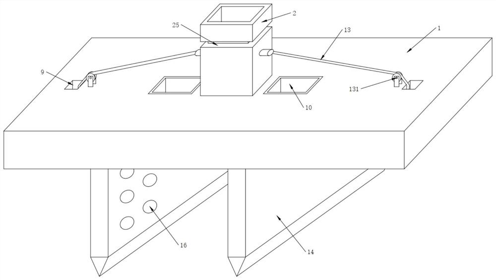
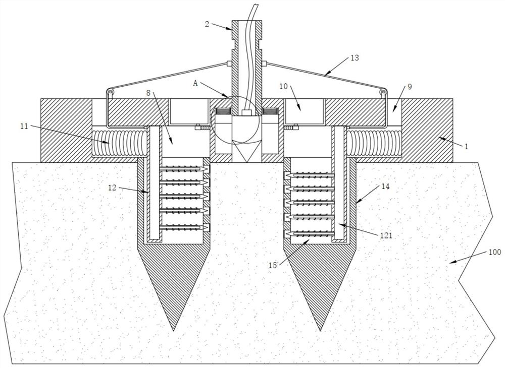
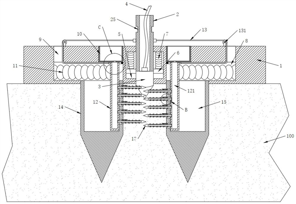
[0029] see Figure 1-8 , the present invention provides a technical solution:

[0030] A distribution transformer grounding structure capable of changing soil resistivity, including a grounding plate 1, a lifting column 2 and a grounding column 3, the lifting column 2 is movably plugged into the grounding plate 1, and the lifting column 2 can move up and down in the grounding plate 1 , there is a clamping groove 25 on the outer wall of the lifting column 2, a...


PUM


Abstract

The invention discloses a distribution transformer grounding structure capable of changing soil resistivity, comprising a grounding plate, a lifting column and a grounding column, the lifting column is movably plugged into the grounding plate, and the grounding column is fixedly connected to the bottom of the lifting column The grounding column is connected with connecting wires; side grooves are symmetrically opened in the grounding plates on both sides of the lifting column, and extruding plates are movable in the side grooves, and the extruding plates are fixedly connected to the lifting column. And the upper end of the extrusion plate is connected with a lifting spring. The present invention can compress and tamp the soil layer between the inserted floors through the cooperative arrangement of the inserted floor and the push plate, so as to achieve the effect of reducing soil resistivity; and at the same time, keep the soil in the The higher the concentration of conductive ions and the water content in the soil, the lower the soil resistivity.

Description

technical field [0001] The invention relates to the technical field of distribution transformers, in particular to a distribution transformer grounding structure capable of changing soil resistivity. Background technique [0002] In the prior art, the publication number is CN 105958224 A. The grounding structure of a distribution transformer includes a grounding plate and a grounding pole. The grounding pole is arranged on the extension line of the grounding plate. The pole includes a cylinder and a connecting piece, the connecting piece is provided with a terminal and / or a wiring hole, and a fixed joint is provided on the grounding plate; the advantage of the present invention is that the grounding pole is set on the extension line of the grounding plate, effectively increasing Since the grounding resistance R is equal to the soil resistivity × conductor length / grounding area, when the grounding area increases, the grounding resistance R decreases correspondingly when the...

Claims


Application Information

Patent Timeline
Patent Type & Authority Patents(China)
IPC IPC(8): H01R4/66
CPCH01R4/66
Inventor 沈文齐沈梦然
Owner 国能荥阳热电有限公司
Why Eureka
Try Eureka