
Method for removing center line shrinkage and controlling center segregation of 280mm*320mm fracture surface high-carbon steel

A technology of central shrinkage cavity and control center, which is applied in the field of continuous casting in the metallurgical industry

Active Publication Date: 2020-07-03
ZENITH STEEL GROUP CORP +1
View PDF12 Cites 8 Cited by
  • Summary
  • Abstract
  • Description
  • Claims
  • Application Information

AI Technical Summary

Problems solved by technology

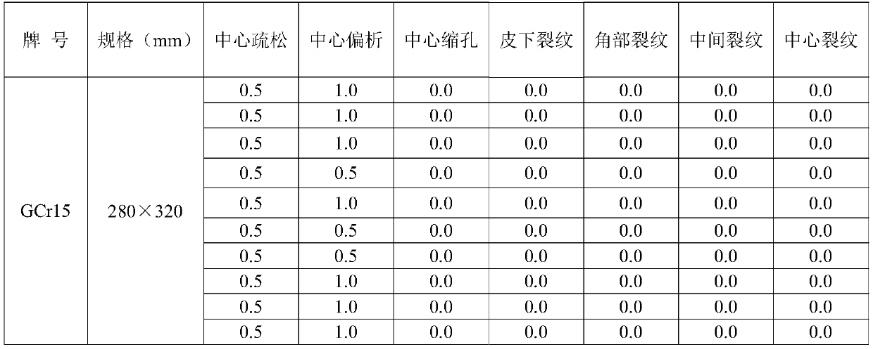
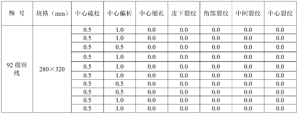
[0003] In order to solve the above slab production problems, the present invention provides a high-carbon steel rectangular slab continuous casting production process that can significantly eliminate the center shrinkage cavity and reduce defects such as center segregation and center porosity, and specifically proposes a high-carbon steel with a cross-section of 280mm×320mm The method of eliminating center shrinkage cavity and controlling center segregation. In this method, the secondary cooling of continuous casting adopts the weak cooling mode. When the solid phase ratio fs in the center of the slab is ≥ 0.55 and the core temperature of the slab is lower than 180°C after the slab solidifies Implement light reduction to solve defects such as shrinkage cavity and center segregation in the core of the slab

Method used


Image

  • Method for removing center line shrinkage and controlling center segregation of 280mm*320mm fracture surface high-carbon steel
  • Method for removing center line shrinkage and controlling center segregation of 280mm*320mm fracture surface high-carbon steel

Examples


Embodiment Construction

[0011] The present invention is described in further detail below in conjunction with embodiment:

[0012] The present invention will be described in further detail below in conjunction with specific examples.

[0013] The soft reduction technology implements multi-roll continuous rolling in the section where the solid phase ratio in the mushy zone of the slab is 0.3-0.8 (the proportion of the solid phase in the mushy zone, when the solid phase ratio is 1, it is equivalent to the complete solidification of the slab). Improve the center segregation of the slab with a small reduction, or adopt heavy reduction technology at the end of solidification, aiming to apply a large reduction in the range of solid phase ratio of 0.8-1.0 in the mushy area of ​​the slab to solve the problem of shrinkage cavity in the core of the slab, but looking for To the real position of the coagulation end is the focus of implementing this technology. In the production of high carbon steel, the mushy z...


PUM


Abstract

The invention discloses a method for removing center line shrinkage and controlling center segregation of 280mm*320mm fracture surface high-carbon steel. Continuous casting secondary cooling adopts alow cooling mode; the relation between the rolling reduction of a soft reduction machine frame and the solid phase rate fs of the center of a cast blank is as follows: when fs is larger than or equalto 0 but smaller than 0.55, the rolling reduction is 0mm, when fs is larger than or equal to 0.55 but smaller than 0.70, the single-roller rolling reduction is 2.0mm, and when fs is larger than or equal to 0.7 but smaller than or equal to 1, the single-roller rolling reduction is 4-5mm; when the temperature of the core of a solidified cast blank is lower than the solidification temperature 110 DEGC, the single-roller rolling reduction is 4-5mm; when the temperature of the core of the solidified cast blank is lower than the solidification temperature 150 DEG C, the single-roller rolling reduction is 2mm; and when the temperature of the core of the solidified cast blank is lower than the solidification temperature 180 DEG C, the single-roller rolling reduction is 0mm. By means of the method, the rolling reduction is controlled through change of the solid phase rate of the center of the cast blank and the temperature of the core of the solidified cast blank, the center line shrinkage isremoved, the central carbon segregation index of the cast blank is controlled to be 0.98-1.10 with the average being 1.06, the center porosity is smaller than or equal to 0.5 grade, and the center line shrinkage is 0 grade.

Description

technical field [0001] The invention relates to a continuous casting process, which can eliminate the central shrinkage cavity of the high-carbon steel with a rectangular billet with a large cross-section by dynamic light reduction, and effectively improve the center segregation and center porosity of the cast billet, and belongs to the continuous casting technical field of the metallurgical industry. Background technique [0002] For large-section high-carbon steel with a side length greater than 200 mm (including rectangles), the theory of central segregation is mainly the "solidification crystal bridge" theory. The shape of the end of the liquid-phase cavity inside the high-carbon steel slab is very sharp. Due to the accumulation of solute, the solute concentration at the tip of the liquid-phase cavity is very high. Sealing the tip of the liquid phase hole blocks the interdiffusion between the tip and other liquid phases, thus forming a solute-rich "small ingot" structure...

Claims


Application Information

Patent Timeline
Patent Type & Authority Applications(China)
IPC IPC(8): B22D11/22B22D11/16
CPCB22D11/16B22D11/225
Inventor 王向红王海洋张健斌于金江
Owner ZENITH STEEL GROUP CORP
Learn More