
Follow-up conveying device of laser processing equipment for continuous cutting

A conveying device and laser processing technology, applied in laser welding equipment, metal processing equipment, welding equipment, etc., can solve problems such as reducing the applicability of machine tools, affecting the stability of sheet materials, and being difficult to meet.

Pending Publication Date: 2020-07-03
国机铸锻机械有限公司
View PDF0 Cites 0 Cited by
  • Summary
  • Abstract
  • Description
  • Claims
  • Application Information

AI Technical Summary

Problems solved by technology

[0002] Laser cutting is the key equipment for metal sheet processing. Traditional laser cutting is to place the prepared sheet in the cutting area of ​​the laser equipment. The cutting area is currently divided into two types: fixed and mobile. The fixed type is generally The sawtooth metal support is used to place the cutting sheet, which is only suitable for fixed cutting of a single sheet, and the bottom surface of the sheet is easy to scratch; the mobile platform mainly follows the movement of the cutting head, and the platform directly affects the upper panel The stability of the material leads to the disadvantage of poor cutting quality. In addition, because the entire platform must be driven to be consistent with the trajectory of the cutting head, it is difficult to meet the current high dynamic corresponding requirements of laser cutting, which reduces the applicability of the machine tool.

Method used


Image

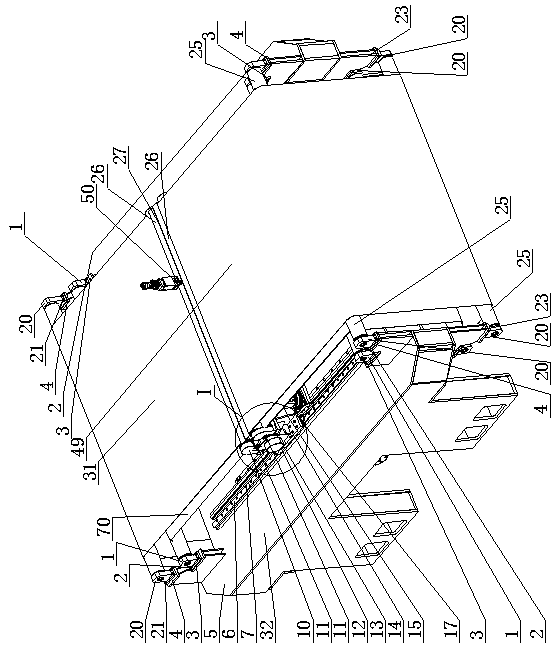
  • Follow-up conveying device of laser processing equipment for continuous cutting
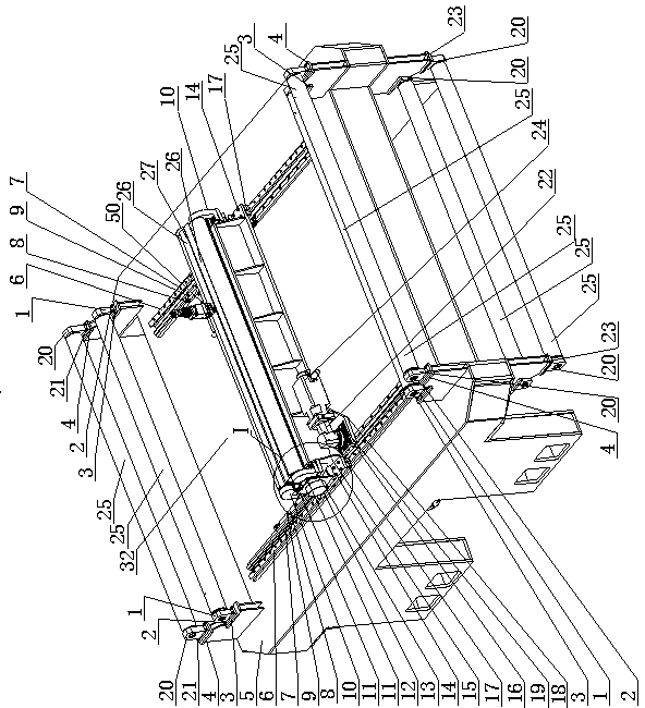
  • Follow-up conveying device of laser processing equipment for continuous cutting
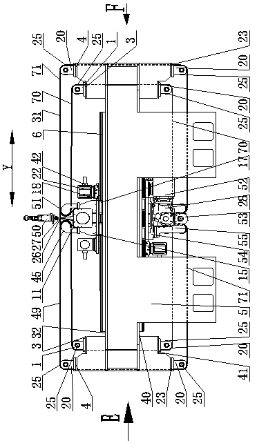
  • Follow-up conveying device of laser processing equipment for continuous cutting

Examples


Embodiment 2

[0070] Embodiment 2: The preparation of this embodiment is the same as that of Embodiment 1 and will not be repeated, except that the arrangement of double conveying devices is adopted.

[0071] Such as Figure 19 and 20 As shown, a continuous cutting laser processing equipment follows the conveying device, which includes a frame 5, and on the top surface of the frame 5, an upper movable frame that can reciprocate relative to the frame 5 is arranged side by side under the drive of the upper beam driving device. Crossbeam 15 is provided with parallel upper beam left driven roller 45 and upper crossbeam right driven roller 51 on moving crossbeam 15, is provided with a plurality of frame driven rollers 25 on frame 5, on described frame driven roller 25 The part corresponding to the belt is set and can rotate independently (coaxial double rollers). On the bottom surface of the frame 5, there is also a lower moving beam 54 that moves back and forth relative to the frame under the ...

Embodiment 3

[0076] Embodiment 3: The similarities between this embodiment and Embodiment 1 will not be repeated, and the difference is that the feeding direction (Y direction) adopts a double-belt arrangement. Such as Figure 24 Shown, a kind of laser processing equipment of continuous cutting follows conveying device, and it comprises frame 5, is provided with on the top surface of frame 5 and can move back and forth with respect to frame under the drive of upper beam driving device under the movable crossbeam 15, Be provided with parallel upper beam left driven roller 45 and upper beam right driven roller 51 on upper moving beam 15, be provided with a plurality of frame driven rollers 25 on frame 5, also be provided with lower beam drive on frame 5 bottom surface Driven by the device, the lower moving crossbeam 54 that reciprocates relative to the frame is provided with the first driving roller 30 and the second driving roller 65 arranged up and down in parallel on the lower moving cros...

Embodiment 4

[0081] Embodiment 4: The similarities between this embodiment and Embodiment 3 will not be described in detail. The difference is that an upper movable crossbeam that can move back and forth relative to the frame is arranged side by side on the top surface of the frame 5 under the drive of the upper crossbeam driving device. 15, on each moving beam 15, be provided with parallel upper beam left driven roller 45 and upper beam right driven roller 51, be provided with a plurality of frame driven rollers 25 on the frame 5, on the frame driven roller 25 is provided with a part corresponding to each belt and can rotate independently (coaxial double rollers). The lower crossbeam 54 that moves back and forth relative to the frame under the drive of the lower crossbeam driving device is also arranged side by side on the bottom surface of the frame 5. Each lower moving crossbeam 54 is provided with a first driving roller 30 and a second driving roller 65 arranged up and down in parallel,...


PUM


Abstract

The invention relates to a follow-up conveying device of laser processing equipment for continuous cutting. The device comprises a rack and an upper moving beam on the rack, wherein an upper beam leftdriven roller and an upper beam right driven roller which are parallel to each other are arranged on the upper moving beam, a plurality of rack driven rollers are arranged on the periphery of the rack, a lower moving beam is arranged below the rack, a connecting mode and a driving mode of the lower moving beam are consistent with a connecting mode and a driving mode of the upper moving beam, twopairs of parallel lower beam driven rollers are arranged on the lower moving beam, a corresponding driving roller is arranged between each pair of lower beam driven rollers, each of input shafts of the two driving rollers is fixedly provided with a corresponding same synchronous gear, the two synchronous gears can mesh with each other for transmission, the input shaft of one of the driving rollerspenetrates through the corresponding synchronous gear and is connected with an output shaft of a driving roller speed reducer through a key, a belt is wound on the rack driven rollers, the upper beamleft driven roller, the upper beam right driven roller, the lower beam driven rollers, the first driving roller and the second driving roller according to a set direction, so that the rollers are connected together.

Description

technical field [0001] The solution relates to a conveying device, in particular to a following conveying device for laser processing equipment capable of realizing stable conveying and high-precision continuous cutting. Background technique [0002] Laser cutting is the key equipment for metal sheet processing. Traditional laser cutting is to place the prepared sheet in the cutting area of ​​the laser equipment. The cutting area is currently divided into two types: fixed and mobile. The fixed type is generally The sawtooth metal support is used to place the cutting sheet, which is only suitable for fixed cutting of a single sheet, and the bottom surface of the sheet is easy to scratch; the mobile platform mainly follows the movement of the cutting head, and the platform directly affects the upper panel The stability of the material leads to the disadvantage of poor cutting quality. In addition, because the entire platform has to be driven in the same trajectory as the cutti...

Claims


Application Information

Patent Timeline
IPC IPC(8): B23K26/70B23K26/38
CPCB23K26/702B23K26/38
Inventor 张建设张凯徐济声倪汉平李玉家臧俊智李娜
Owner 国机铸锻机械有限公司
Learn More