Method for manufacturing chemical tank

A manufacturing method and technology of chemical tanks, applied in the direction of manufacturing tools, metal processing, metal processing equipment, etc., can solve problems such as endangering the safety of operators, tank rotation, poor stability, etc., to improve the degree of intelligence and reduce labor intensity , the effect of reducing the risk

Active Publication Date: 2020-07-03
武汉伊斯坎机电技术有限公司
View PDF7 Cites 9 Cited by
  • Summary
  • Abstract
  • Description
  • Claims
  • Application Information

AI Technical Summary

Problems solved by technology

[0003] However, in the current manufacturing process of chemical tanks, it is necessary to manually dock the tank body and end cover of the chemical tank. Due to the large volume and weight of the tank body and the end cover, it is necessary to manually fix the tank body with the help of existing fixtures. For tanks of different specifications, manual adjustment of the jig is required. Manual control of the jig has poor stability in fixing the tank and cannot assist the rotation of the tank during the welding operation, which affects the convenience of the welding operation. It is necessary to manually use tools to control the chemical tank. The end cover is connected with the tank body. The error of manual control of the connection between the end cover and the tank body is large. The adjustment of the manual control end cover requires locking and clamping of the end cover. The stability of manual control locking and clamping is poor. Accidents cause the end cap to fall, endangering the safety of workers, and reducing the efficiency of chemical tank manufacturing, low intelligence and other problems

Method used


Image

  • Method for manufacturing chemical tank
  • Method for manufacturing chemical tank
  • Method for manufacturing chemical tank

Examples


Embodiment Construction

[0031] The embodiments of the present invention will be described in detail below with reference to the accompanying drawings, but the present invention can be implemented in many different ways defined and covered by the claims.

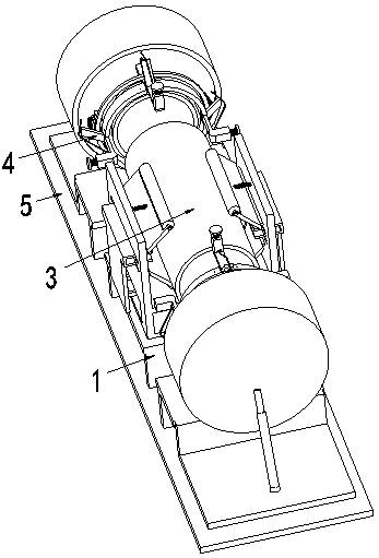
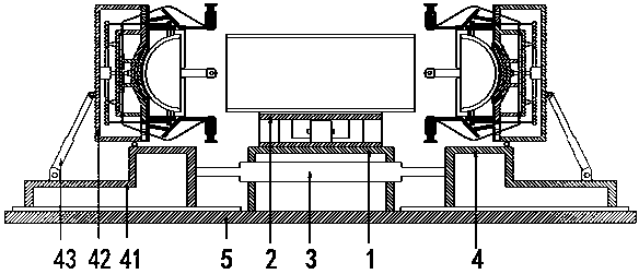
[0032] Such as Figure 1 to Figure 6 Shown, a kind of chemical tank manufacturing method, it has used a kind of chemical tank assembling fixture, this chemical tank assembling fixture, comprises bottom plate 5, is arranged on the placement frame 1 on the bottom plate 5, is arranged on the tank body support on the placement frame 1 Device 2, the first biaxial cylinder 3 arranged in the middle of the placement frame 1, and the end cover support device 4 installed on the front and rear sides of the first biaxial cylinder 3;

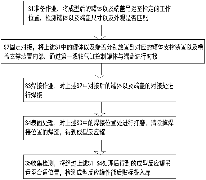
[0033] The manufacturing and processing steps of the chemical tank using the chemical tank assembly jig are as follows:

[0034] S1 preparation operation, lift the formed tank body and end cap to the designated working position, ...


PUM


Abstract

The invention relates to a method for manufacturing a chemical tank, which adopts a chemical tank assembling clamp. The chemical tank assembling clamp comprises a bottom plate, a placing rack, a tankbody supporting device, a first double-axis air cylinder and end cover supporting devices, wherein the placing rack is arranged on the bottom plate; the tank body supporting device is arranged on theplacing rack; the first double-axis air cylinder is arranged on the middle part of the placing rack; and the end cover supporting devices are mounted on the front side and the back side of the first double-axis air cylinder. By the method, the problems that the tank body of the chemical tank and the end cover need to be butted manually in the manufacturing process of the chemical tank at present,the tank body needs to be fixedly manually by virtue of an existing clamp due to large volume and weight of the tank body and the end cover, the clamp needs to be adjusted manually for the tank bodieswith different specifications, the stability of fixing the tank body by manually controlling the clamp is low, rotation of the tank body in the welding operation cannot be assisted, convenience on the welding operation is affected, the end cover and the tank body of the chemical tank need to be controlled manually by virtue of a tool for connection, and the connection error of the end cover and the tank body by manual control is large can be solved.

Description

technical field [0001] The invention relates to the technical field of chemical equipment, in particular to a method for manufacturing a chemical tank. Background technique [0002] Chemical storage tanks used in chemical industry production, chemical storage tanks, chemical mixing tanks, chemical spherical tanks, chemical iron tanks, chemical reaction tanks, chemical neutralization tanks, etc., the general term for tanks used in chemical production, different types of chemical tanks The structural shape of the chemical tank is quite different, and there are big differences in the processing methods for chemical tanks of different specifications. The volume and weight of large chemical tanks are relatively large. In the process of processing and manufacturing, it is necessary to prepare the components of the chemical tank, fix the docking, Welding operations, surface treatment, and collection and testing are multiple steps, among which the fixed butt joint of chemical tank c...

Claims


Application Information

Patent Timeline
Patent Type & Authority Applications(China)
IPC IPC(8): B23K31/02B23K37/053B23K37/00B23P15/00
CPCB23K31/02B23K37/00B23K37/053B23P15/00B23K2101/125
Inventor 王俊峰
Owner 武汉伊斯坎机电技术有限公司
Why Eureka
Try Eureka