Steel slag heat treatment and method

A technology of heat treatment system and steel slag, which is applied in the direction of separation method, chemical instrument and method, combined device, etc., can solve the problems of plant structure corrosion, affecting the workshop environment, and harsh working environment, so as to improve the service life, purify the working environment, and prevent dusty effect

Inactive Publication Date: 2020-07-03
无锡澄天环境科技有限公司
View PDF1 Cites 2 Cited by
  • Summary
  • Abstract
  • Description
  • Claims
  • Application Information

AI Technical Summary

Problems solved by technology

However, the process has the following problems in the process of operation: 1) Since the slag dumping tank is open, when spraying water into the slag dumping tank, a large amount of smoke will be directly discharged into the workshop, affecting the environment of the workshop ;2) During the slag cleaning operation, the temperature in the middle layer of the slag pool is high, and when the loader is used to shovel the slag, a large amount of dust will be generated floating in the air, and the working environment is relatively harsh, which affects the health of the staff; The main component is tricalcium silicate. The steam generated during the slag dumping process will carry a large amount of smoke and dust and adhere to the structure of the plant. Over time, it will cause corrosion of the plant structure and shorten the service life of the plant.

Method used


Image

  • Steel slag heat treatment and method
  • Steel slag heat treatment and method

Examples


Embodiment Construction

[0023] The present invention will be further described in detail below in conjunction with the accompanying drawings and specific embodiments.

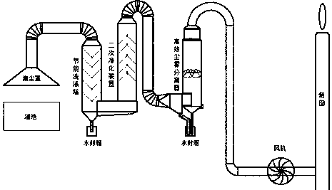
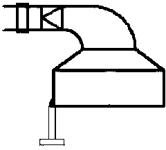
[0024] Iron and steel slag heat treatment system and method, its structure is as follows figure 1 As shown, including slag pool, dust hood and flue gas treatment mechanism, fan and chimney. The slag pool is used to treat steel and steel slag by hot-splashing gravel. The dust collection hood is set above the slag pool to suck in smoke and water vapor. The smoke treatment mechanism is connected to the dust collection hood through pipes to absorb The flue gas and water vapor are processed, and the fan is installed on the pipe connecting the flue gas treatment mechanism and the chimney, which is used to provide negative pressure for the dust collection hood to inhale the flue dust, and discharge the treated clean flue dust from the chimney.

[0025] The pipeline is made of steel and arranged on the factory column in the factory building....


PUM


Abstract

The invention discloses a steel slag heat treatment and method. The system comprises a slag basin for carrying out hot pouring stone breaking treatment on steel slag. A dust collecting cover for sucking smoke and water vapor is arranged above the slag basin, and the dust collecting cover is connected with a smoke treatment mechanism for treating the smoke and the water vapor sucked into the dust collecting cover through a pipeline, and the gas outlet end of the smoke treatment mechanism is connected with a chimney for exhausting treated smoke through a pipeline. A fan for providing negative pressure for the dust collecting cover for sucking the smoke is arranged on the pipeline at the front end of the chimney. The pipeline is arranged on a plant column in a plant, the pipeline is inclineddownwards, and a drain valve for controlling drainage is arranged at the lower end of the pipeline. According to the steel slag heat treatment and method, the vapor and dust generated during slag pouring and slag removing are collected and treated, the treated dust-free smoke is exhausted through the chimney, the dust can be effectively prevented from floating in a workshop, dust overflowing in the workshop is avoided, the operation environment of the workshop is purified, and the service life of the plant is prolonged.

Description

technical field [0001] The invention relates to the technical field of hot furnace steel slag treatment, in particular to a steel and steel slag heat treatment system and method. Background technique [0002] The slag-splashing pool is used to hotly pour gravel across the steel-making slag. After the slag is discharged from the steel-making converter, the slag pot is moved to the side of the slag-splashing pool. It is necessary to use a crane to lift the slag pot to pour it into the open slag-splashing pool. Slag, after the slag pool is full, spray a large amount of cooling water into the slag pool. There is a filter layer at the bottom of the slag pool, which can discharge the unevaporated residual water out of the slag pool. After the steel slag is cooled, use a loader to shovel the steel slag Pick up, load and transport away. [0003] This process is to spray limited water on the slag when the slag is higher than the quenchable temperature, so that the temperature stress...

Claims


Application Information

Patent Timeline
IPC IPC(8): C21B3/06C21B3/08B01D5/00B01D50/00B01D53/00
CPCB01D5/00B01D50/00B01D53/00C21B3/06C21B3/08C21B2400/024C21B2400/05C21B2400/07Y02W30/50
Inventor 郭徽
Owner 无锡澄天环境科技有限公司
Why Eureka
Try Eureka