
Large shield subway station structure and construction method thereof

A subway station and shield technology, which is applied in underground chambers, earthwork drilling, wellbore lining, etc., can solve the problems of large engineering quantity and coordination difficulty, great influence of geological conditions, and low degree of mechanization, so as to make full use of space, Reasonable layout and good mechanical performance

Pending Publication Date: 2020-07-03
CHINA RAILWAY SIYUAN SURVEY & DESIGN GRP
View PDF0 Cites 1 Cited by
  • Summary
  • Abstract
  • Description
  • Claims
  • Application Information

AI Technical Summary

Problems solved by technology

The underground excavation method is greatly affected by geological conditions, the degree of mechanization is low, manual excavation and construction, the risk is high, and the quality is not high; the open excavation method requires open and large excavation. , mountains, buildings, etc.), traffic relief, pipeline relocation, demolition and land acquisition, river and mountain relocation, etc., the project volume and coordination are huge, the investment is quite high, and the implementation is extremely difficult
[0003] At the same time, the existing cross-sectional structure only relies on the segment as the side wall, the strength needs to be improved, and water leakage is prone to occur under some conditions

Method used


Image

  • Large shield subway station structure and construction method thereof
  • Large shield subway station structure and construction method thereof
  • Large shield subway station structure and construction method thereof

Examples


Embodiment Construction

[0039] The principles and features of the present invention are described below in conjunction with the accompanying drawings, and the examples given are only used to explain the present invention, and are not intended to limit the scope of the present invention. In the following paragraphs the invention is described more specifically by way of example with reference to the accompanying drawings. Advantages and features of the present invention will be apparent from the following description and claims. It should be noted that all the drawings are in a very simplified form and use imprecise scales, and are only used to facilitate and clearly assist the purpose of illustrating the embodiments of the present invention.

[0040] It should be noted that when a component is said to be "fixed" to another component, it can be directly on the other component or there can also be an intervening component. When a component is said to be "connected" to another component, it may be directl...


PUM


Abstract

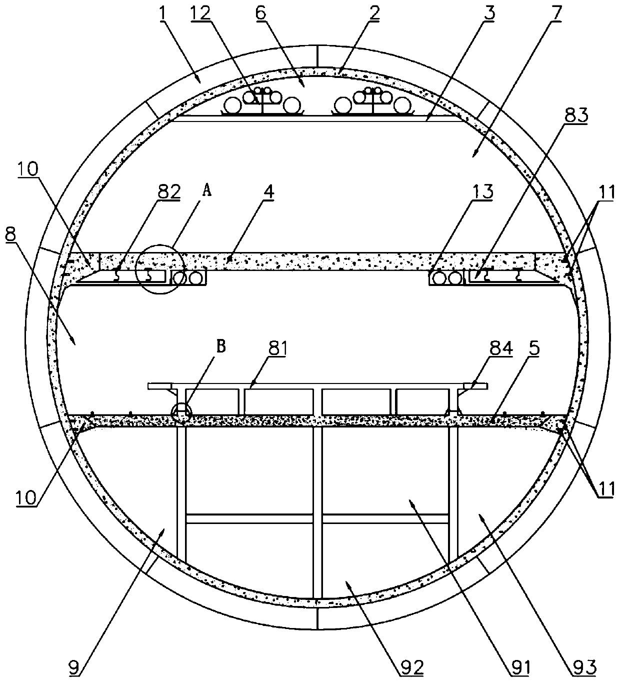
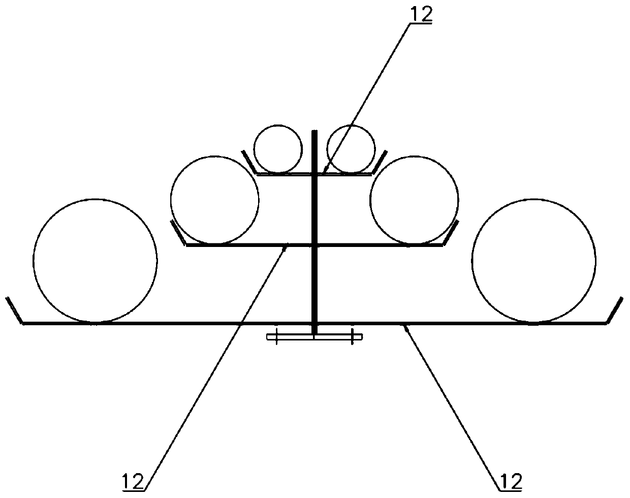
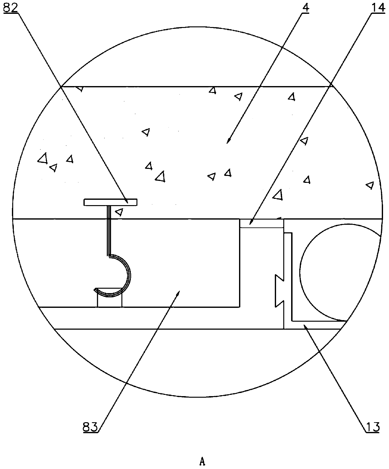
The invention relates to a large shield subway station structure. The large shield subway station structure comprises a plurality of sections of tube segments; concrete layers are arranged on the inner sides of the tube segments; waterproof layers are arranged between the concrete layers and the tube segments; subway station space is formed within the concrete layers; top plates, middle plates and bottom plates are connection into the concrete layers; the subway station space is divided into a pipeline layer, a station hall layer, a platform layer and a functional layer; thickening parts areintegrally manufactured at the end parts, close to the concrete layers, of the middle plate and the bottom plate; the platform layer comprises a prefabricated platform positioned in the middle and subway tracks on two sides of the prefabricated platform; at least one row of hooks are buried at the bottom and above the subway tracks; the hooks are connected with an air duct; the inner sides of thesubway tracks are provided with evacuation channels; a plurality of partition walls are arranged in the functional layer; and each partition wall is divided into an equipment room, a pipeline room anda drainage room; The invention also relates to a construction method of the large shield subway station structure. The construction method comprises six steps. The large shield subway station structure can greatly improve the space utilization rate of the subway station, and effectively solves the problem of constructing the subway station by tunneling under complex environmental conditions.

Description

technical field [0001] The invention relates to the technical field of underground engineering, in particular to a large shield subway station structure and a construction method thereof. Background technique [0002] At present, shields are used to construct subway stations mainly in the form of double horseshoe and three-circle shields, etc. The cross-sectional form requires at least two advances of the shield to form a cross-sectional profile, and the installation of segments is difficult and the space utilization rate is low; Some construction methods generally include open-cut method and under-cut method. The underground excavation method is greatly affected by geological conditions, the degree of mechanization is low, manual excavation and construction are risky, and the quality is not high; , mountains, buildings, etc.), traffic relief, pipeline relocation, demolition and land acquisition, river and mountain relocation, etc., the project volume and coordination are h...

Claims


Application Information

Patent Timeline
IPC IPC(8): E21D11/00E21D11/08E21D11/10E21D11/38E21F17/02E21F11/00E21D9/14
CPCE21D9/14E21D11/003E21D11/08E21D11/10E21D11/38E21F11/00E21F17/02
Inventor 欧阳冬张建明李成亮刘习超柯尉王华兵罗会平徐军林周兵余行张波毛良根
Owner CHINA RAILWAY SIYUAN SURVEY & DESIGN GRP
Learn More