
Liquid crystal module hole inner wall light leakage detection method and device

A liquid crystal module and detection equipment technology, applied in the direction of optical instrument testing, optics, measuring devices, etc., can solve the problems of increasing the size of the equipment, being invisible, and bulky, and achieving the reduction of occupied space, convenient adjustment, and adaptability Good results

Pending Publication Date: 2020-07-03
高视科技(苏州)股份有限公司
View PDF10 Cites 2 Cited by
  • Summary
  • Abstract
  • Description
  • Claims
  • Application Information

AI Technical Summary

Problems solved by technology

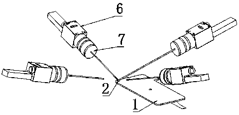
In the traditional inspection scheme, when the CCD camera 6 takes pictures of the light leakage defect 3 of the liquid crystal module 1 under test, the optical lens of the CCD camera 6 often needs to be aligned with the light leakage defect of the liquid crystal module 1 under test, and the circle of the liquid crystal module 1 The light leakage defect 3 in the hole 2 cannot be photographed when the CCD camera 6 is perpendicular to the surface of the liquid crystal module 1 to be tested, and the required angle can only be achieved by tilting the CCD camera 6
[0007] (1) Under the same environment, if the light leakage defect 3 in the round hole 2 of the tested liquid crystal module 1 is in different positions, it is necessary to use multiple camera lenses or a camera rotating around the round hole 2 to shoot, and the cost is very high
[0009] (3) Under the same environment, if the optical imaging conditions are relatively complex, and the object distance required by the CCD camera 6 is very large, the space occupied by this solution after installation is very large, which increases the size of the equipment

Method used


Image

  • Liquid crystal module hole inner wall light leakage detection method and device
  • Liquid crystal module hole inner wall light leakage detection method and device
  • Liquid crystal module hole inner wall light leakage detection method and device

Examples


Embodiment 1

[0043] see Figure 4 , a method for detecting light leakage on the inner wall of a liquid crystal module hole of the present invention, comprising the following steps:

[0044] (1) Lay the liquid crystal module 1 under test flat, so that the round hole 2 of the liquid crystal module 1 under test faces the detection direction;

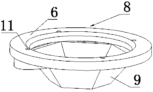
[0045] (2) In the detection direction of the round hole 2 of the liquid crystal module 1 under test, a mirror 8 and a CCD camera 6 are arranged in sequence; when there is a light leakage defect 3 on the side wall of the round hole 2, the light at the part of the light leakage defect 3 passes through the mirror After the reflection of 8, enter in the optical lens 7 of CCD camera 6;

[0046] (3) The CCD camera 6 takes photos, and performs image processing through the image processing module of the computer to judge whether there are image features generated by the light leakage defect 3 in the photos, and then judge whether there is a light leakage defec...

Embodiment 2

[0059] see Figure 4 , a detection device for detecting light leakage on the inner wall of the liquid crystal module hole of the present invention for realizing the above method for detecting light leakage on the inner wall of the hole of the liquid crystal module, comprising a CCD camera 6 and a mirror 8, and the mirror 8 is arranged on the liquid crystal module to be tested Above the circular hole 2 of 1, the CCD camera 6 is arranged above the reflector 8; when there is a light leakage defect 3 on the side wall of the circular hole 2, the light at the position of the light leakage defect 3 is reflected by the reflector 8 and enters the CCD The optical lens 7 of the camera 6 is easy to adjust, low in cost and small in space, and the CCD camera 6 or the optical lens 7 is not easy to interfere with the liquid crystal module 1 under test.

[0060] see Figure 4-5 , the reflector 8 includes an annular mirror surface 9, the radial size of the annular mirror surface 9 gradually in...

Embodiment 3

[0069] see Figure 7 The difference between this embodiment and Embodiment 2 is that in the detection device for light leakage on the inner wall of the liquid crystal module hole in this embodiment, the mirror surface of the annular mirror 9 is a curved surface, and the transverse section of the annular mirror 9 is a circle. shape.

[0070] Other implementations of this embodiment are the same as those of Embodiment 2 except for the above.


PUM


Abstract

The invention discloses a liquid crystal module hole inner wall light leakage detection method and device. The method comprises the following steps (1) of enabling a detected liquid crystal module tobe placed flatly, and enabling a circular hole of the detected liquid crystal module to face a detection direction; (2) sequentially arranging a reflecting mirror and a CCD (Charge Coupled Device) camera in the detection direction of the circular hole of the detected liquid crystal module; when a side wall of the circular hole has a light leakage defect, the light of a light leakage defect part enters an optical lens of the CCD camera after being reflected by the reflector; and (3) taking a picture by the CCD camera, carrying out image processing through an image processing module of the computer, judging whether image characteristics generated by the light leakage defect part exist in the picture or not, and further judging whether light leakage exists on an inner wall of the detected liquid crystal module hole or not. The liquid crystal module hole inner wall light leakage detection method and the liquid crystal module hole inner wall light leakage detection equipment have the advantages of small equipment occupied space and low cost, and the camera position is simple and convenient to adjust and does not interfere with a measured object during adjustment.

Description

technical field [0001] The invention relates to a detection method and detection equipment for a liquid crystal module, in particular to a detection method and detection equipment for light leakage on the inner wall of a liquid crystal module hole. Background technique [0002] With the development of liquid crystal technology, liquid crystal panels have rapidly become the leading role in the display market with the characteristics of high resolution, small size, light weight, no radiation, flat panel and low power consumption, from mobile phones to portable game consoles, from industrial equipment to Liquid crystal modules are ubiquitous in many fields, such as manual operation platform to bank self-service equipment ATM (Automatic Teller Machine). And digging holes in the screen of the notebook computer, and placing the camera lens below, so as to increase the utilization rate of the screen and make it beautiful. After the liquid crystal module is cut and dug, due to fact...

Claims


Application Information

Patent Timeline
Patent Type & Authority Applications(China)
IPC IPC(8): G02F1/13G01M11/02
CPCG02F1/1309G01M11/0278G01M11/0207
Inventor 吴江许伟丽周波
Owner 高视科技(苏州)股份有限公司
Learn More