Antenna device and electronic equipment

An antenna device, feeding technology, applied in the direction of antennas, electrical components, etc.

Active Publication Date: 2020-07-03
GUANGDONG OPPO MOBILE TELECOMM CORP LTD
View PDF12 Cites 2 Cited by
  • Summary
  • Abstract
  • Description
  • Claims
  • Application Information

AI Technical Summary

Problems solved by technology

[0003] The application provides an antenna device and electronic equipment, which can solve the problem of adjusting the beam radiation direction of the antenna device while saving space

Method used


Image

  • Antenna device and electronic equipment
  • Antenna device and electronic equipment
  • Antenna device and electronic equipment

Examples


Embodiment Construction

[0032] In order to make the objectives, technical solutions, and advantages of the present application clearer, the following will further describe the embodiments of the present application in detail with reference to the accompanying drawings.

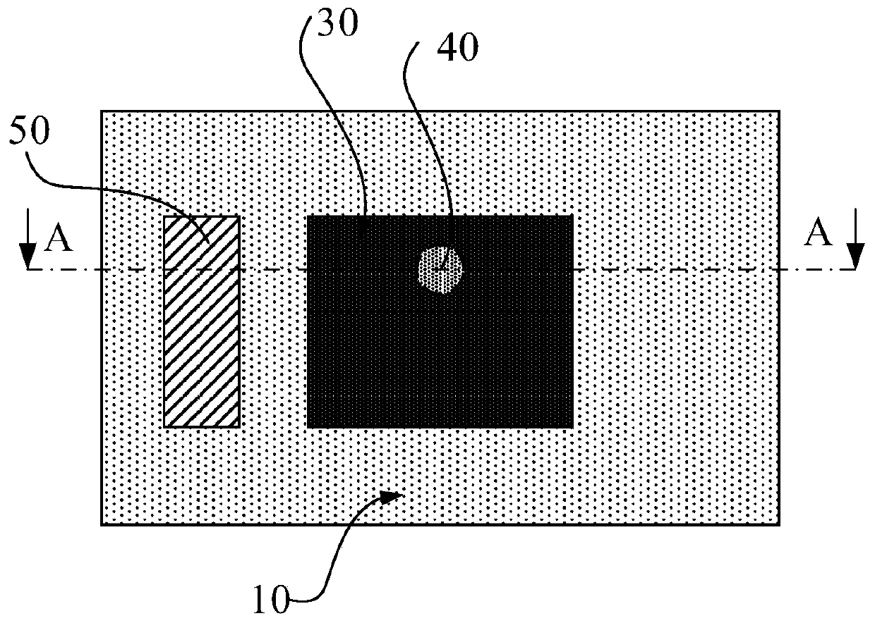
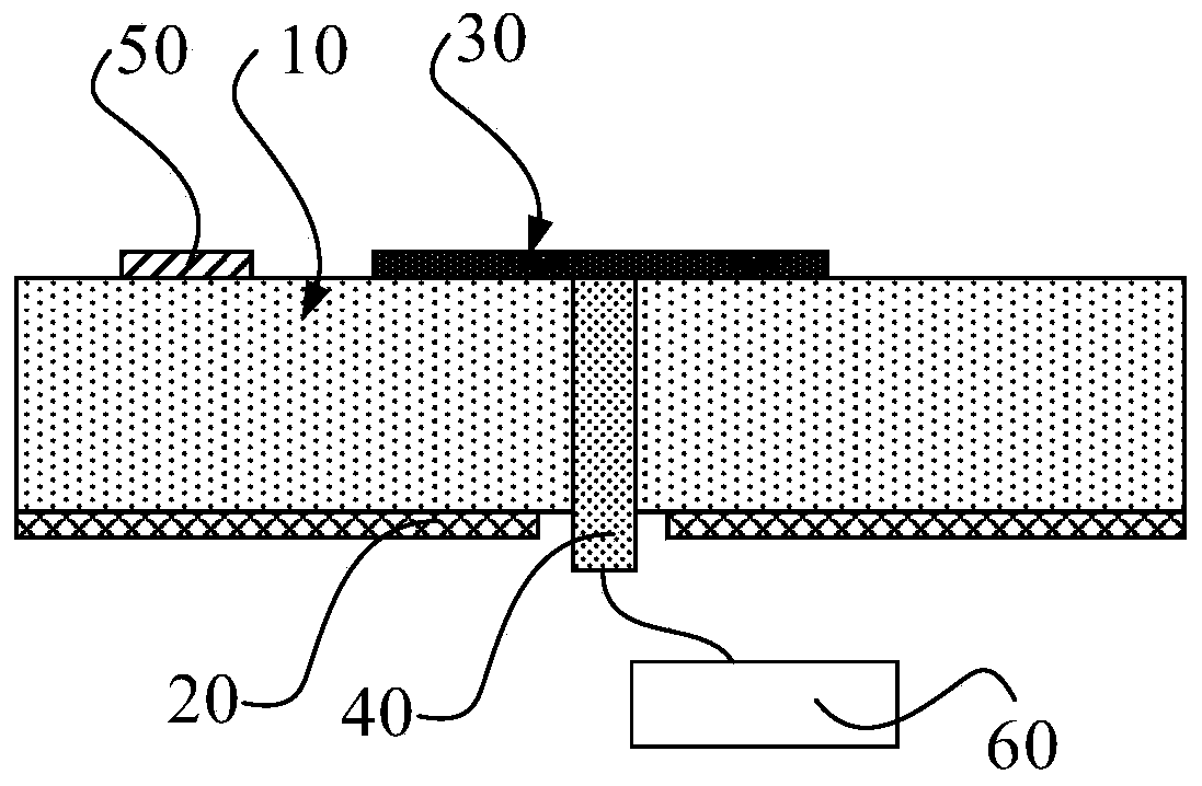
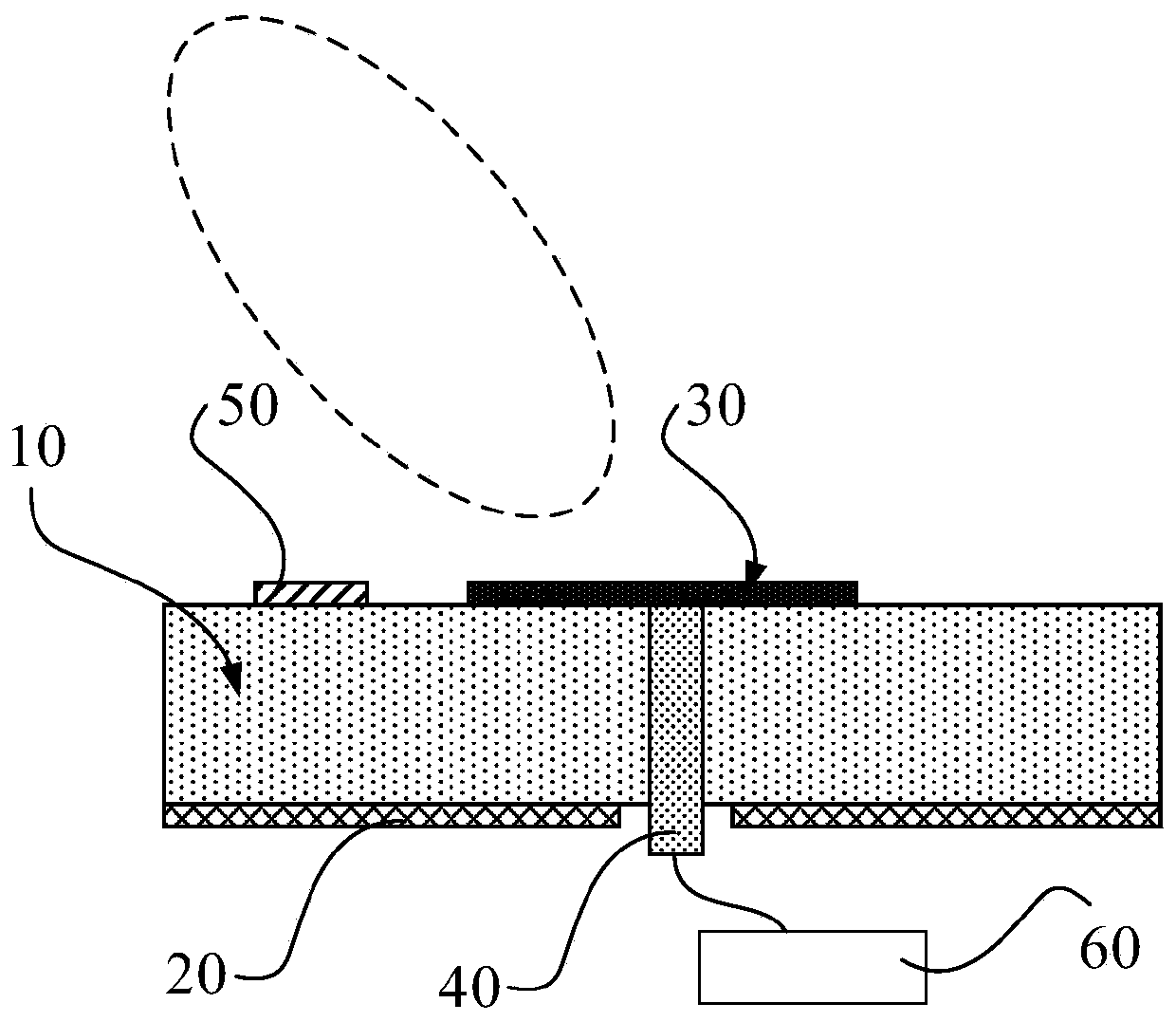
[0033] figure 1 Illustrates a schematic structural diagram of an antenna device according to an embodiment of the present application, figure 2 Illustrates an A-A cross-sectional schematic diagram of an antenna device according to an embodiment of the present application. Such as figure 1 with figure 2 As shown, the antenna device includes at least one dielectric substrate 10, a grounded metal layer 20, a radiation patch 30, a first feed structure 40, a first deflection patch 50, and a radio frequency chip 60; a grounded metal layer 20, at least one layer The dielectric substrate 10 and the radiation patch 30 are stacked, the first feeding structure 40 penetrates at least one layer of the dielectric substrate 10, the first end of the f...


PUM


Abstract

The invention discloses an antenna device and electronic equipment, and belongs to the technical field of antennas. The antenna device comprises at least one layer of dielectric substrate, a groundingmetal layer, a radiation patch, a first feed structure, a first deflection patch and a radio frequency chip, the grounding metal layer, the at least one layer of dielectric substrate and the radiation patch are stacked. The first feed structure penetrates through the at least one layer of dielectric substrate, a first end of the first feed structure is connected with the radiation patch, a secondend of the first feed structure penetrates through the grounding metal layer and is electrically connected with the radio frequency chip, and a first excitation signal fed by the radio frequency chipis used for exciting a radiation beam of the radiation patch; the first deflection patch is fixed to the first side of the radiation patch. When the radiation patch radiates the wave beam, the deflection of the wave beam radiation direction is realized through different forms (crystalline state and amorphous state) of the first deflection patch, the adjustment of the wave beam radiation directionis realized, and the space coverage of the antenna device is improved.

Description

Technical field [0001] This application relates to the field of antenna technology, and in particular to an antenna device and electronic equipment. Background technique [0002] At present, in order to ensure the antenna performance of the electronic device during the use of the electronic device, an antenna device is fixedly installed. Due to the fixed arrangement of the antenna device, the radiation direction of the beam of the antenna device is fixed. In this way, it is difficult to adjust the beam radiation direction through the antenna device to improve the spatial coverage of the antenna device. Summary of the invention [0003] The present application provides an antenna device and electronic equipment, which can solve the problem of adjusting the beam radiation direction of the antenna device while saving space. The technical solution is as follows: [0004] In one aspect, an antenna device is provided. The antenna device includes at least one dielectric substrate, a gro...

Claims


Application Information

Patent Timeline
Patent Type & Authority Applications(China)
IPC IPC(8): H01Q3/00
CPCH01Q3/00H01Q19/005H01Q1/364H01Q3/44H01Q9/0414H01Q5/335
Inventor 雍征东
Owner GUANGDONG OPPO MOBILE TELECOMM CORP LTD
Why Eureka
Try Eureka