Gas-liquid-solid multi-effect separator

A solid-liquid separator, gas-liquid-solid technology, used in separation methods, dispersed particle separation, chemical instruments and methods, etc., can solve problems such as single function, incomplete gas-liquid separation, and inability to effectively separate solid and oil impurities.

Active Publication Date: 2020-07-07
QINGDAO UNIV OF SCI & TECH
View PDF9 Cites 3 Cited by
  • Summary
  • Abstract
  • Description
  • Claims
  • Application Information

AI Technical Summary

Problems solved by technology

[0003] The embodiments of the present invention are used to solve the problems and deficiencies of the existing gas-liquid separator, such as incomplete gas-liquid separation, single function and inability to ef

Method used


Image

  • Gas-liquid-solid multi-effect separator
  • Gas-liquid-solid multi-effect separator
  • Gas-liquid-solid multi-effect separator

Examples


Embodiment 1

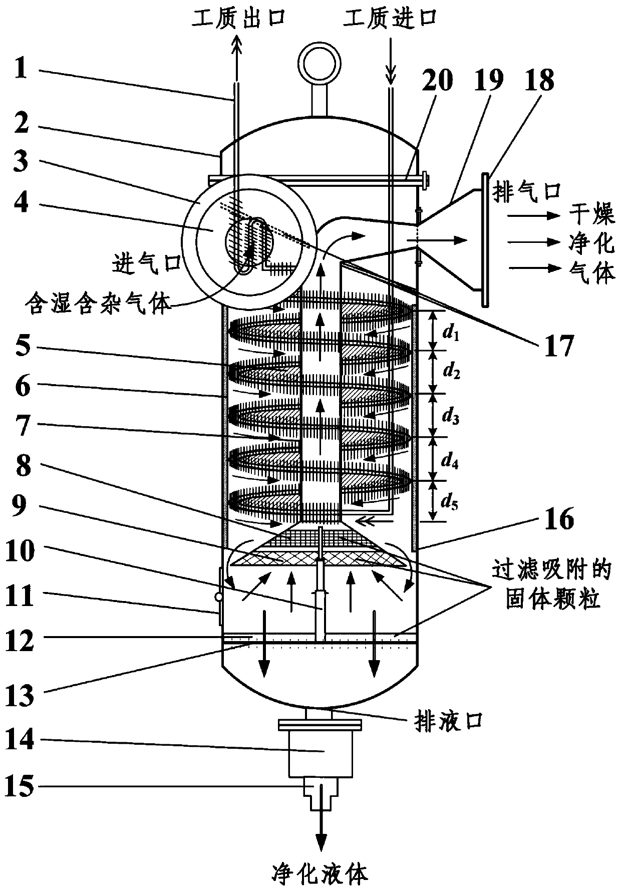
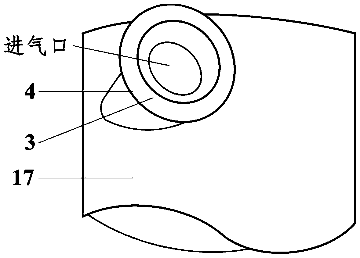
[0039] like Figure 1 to Figure 3 As shown, the embodiment of the present invention provides a gas-liquid-solid multi-effect separator, including a housing, an inlet pipe, an exhaust pipe, a reversing plate, a spiral plate, a reversing pipe, a heat exchanger, a filter screen, a filter Adsorber and solid-liquid separator; the intake pipe 4 is a tapered reducing pipe, which is arranged on the upper part of the shell 16 and is tangent to the circumference of the shell 16 to realize tangential air intake and acceleration; the spiral plate 5 is provided with a heat exchange The device 1 is set between the reversing tube 7 and the shell 16, and is fixed on the reversing tube 7. The gas-liquid separation is realized during the flow of the gas along the spiral plate; the heat exchanger 1 is a finned heat exchange tube, which increases the gas The liquid separation area and the heat dissipation area accelerate the gas collision and cooling and dehumidification; the filter screen 9 is s...

Embodiment 2

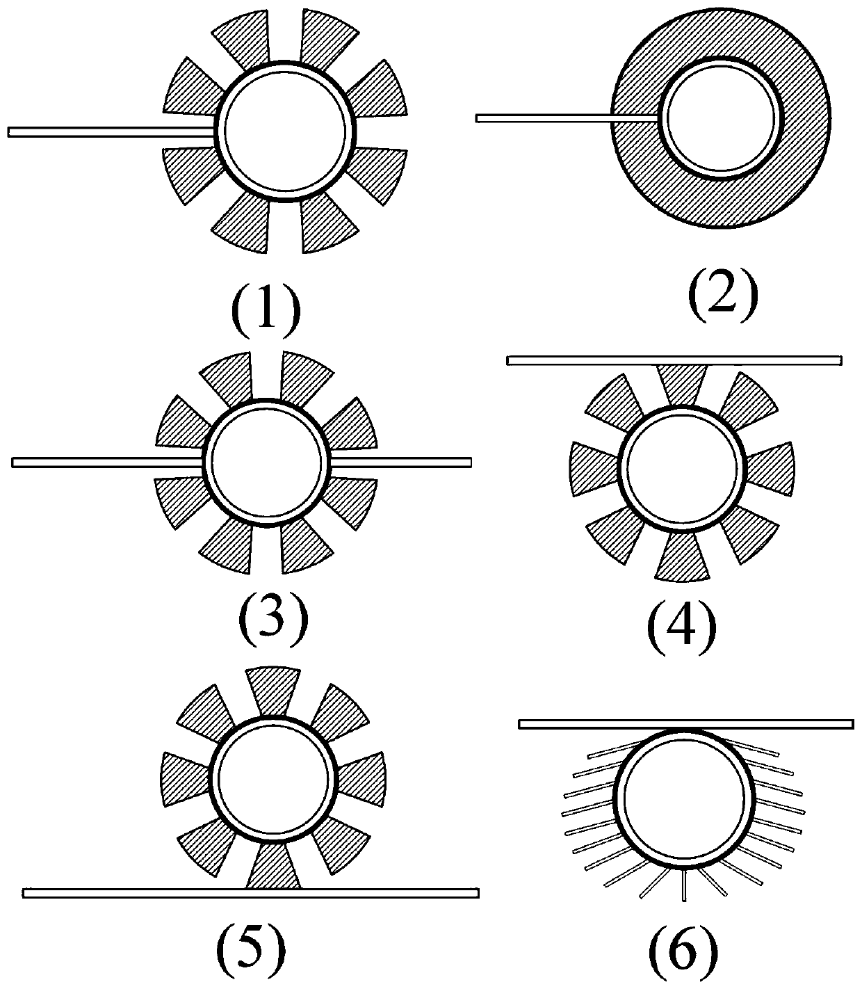
[0058] The difference between this embodiment and the first embodiment lies in that the horizontal section of the reversing tube is different. like Figure 4 As shown, in this embodiment, the horizontal pipe part of the reversing pipe is a pipe with equal cross-section, and the structures and beneficial effects of other parts not described are the same as those in Embodiment 1. The advantage of this embodiment is that the equal-section pipe is easy to manufacture.

Embodiment 3

[0060] The difference between this embodiment and the first embodiment lies in that the position of the intake pipe and the structure of the reversing pipe are different. like Figure 5 As shown, in this embodiment, the intake pipe is located on one side of the housing and is coaxial with the exhaust pipe; the reversing pipe only has a vertical section, and the purified gas directly enters through the reversing pipe, which is composed of the housing, the reversing plate and the upper end cover. In the large space cavity, and then discharged through the exhaust pipe. Other structures and beneficial effects not described are the same as those in Embodiment 1. The advantage of this embodiment is that the intake pipe and the exhaust pipe are coaxial, and the processing is convenient.


PUM


Abstract

The invention relates to the technical field of filtration, purification and purification, and discloses a gas-liquid-solid multi-effect separator which comprises a shell, a gas inlet pipe, a gas outlet pipe, a spiral plate, a reversing pipe, a heat exchanger, a filter screen mesh, a filter adsorber and a solid-liquid separator, wherein the tapered gas inlet pipe is arranged at the upper part of the shell and is tangent to the circumference of the shell to realize tangential gas inlet and gasflow acceleration; the heat exchanger is arranged on the spiral plate and fixed to the reversing pipe,and gas-liquid separation is achieved in the flowing process of gas along the spiral plate; the heat exchanger is a finned tube type heat exchange tube and is used for accelerating gas cooling and dehumidification; the filter screen mesh and the filter adsorber are sequentially arranged at the lowermost end in the reversing pipe from top to bottom and are used for filtering and adsorbing liquid and solid in the gas; the solid-liquid separator is arranged at the lower part of the shell to realize solid-liquid separation; the horizontal section of the reversing pipe is a diverging and reducing pipe, and the diverging type gas outlet pipe is arranged on the other side of the shell and is coaxial with the gas inlet pipe. The gas-liquid-solid multi-effect separator provided by the invention realizes thorough separation and purification of gas and liquid, and is high in separation efficiency and reliable and stable in work.

Description

technical field [0001] The invention relates to the technical field of filtration and purification, in particular to a gas-liquid-solid multi-effect separator. Background technique [0002] The gas-liquid separator is mainly used in the drying of wet gas or the extraction and recovery of gas-containing liquid, as well as in various industrial and civil occasions such as gas removal, oil-gas separation, and liquid removal. Traditional gas-liquid separators perform gas-liquid separation, especially the gas-liquid separation of high-temperature gases. There are problems such as incomplete gas-liquid separation, inability to effectively separate solids and oil impurities, and solids in the separated liquid. Often a separator cannot To meet the separation requirements, multi-stage separation and other processes need to be used together, which makes the system complex, bulky and difficult to maintain. In addition, the gas-liquid separator in the prior art has insufficient filteri...

Claims


Application Information

Patent Timeline
IPC IPC(8): B01D50/00
CPCB01D50/20
Inventor 孟祥文张江辉刘杰
Owner QINGDAO UNIV OF SCI & TECH
Why Eureka
Try Eureka