Mechanical arm based on pneumatic control surface and working method thereof

A working method and a technology of a robotic arm, applied to aircraft parts, electric controllers, controllers with specific characteristics, etc., can solve problems such as low precision, sub-machine attitude, and slow position response

Active Publication Date: 2020-07-07
NANJING UNIV OF AERONAUTICS & ASTRONAUTICS
View PDF4 Cites 1 Cited by
  • Summary
  • Abstract
  • Description
  • Claims
  • Application Information

AI Technical Summary

Problems solved by technology

[0006] The invention provides a mechanical arm based on a pneumatic rudder surface and its working method, which can be applied to a variety of aerial docking operations, and the corresponding control speed is fast, the docking is accurate, safe and reliable, and the safety and reliability of the aerial docking are improved. Improve the docking efficiency; solve the problem of slow attitude and position response and low precision of the sub-machine when the exist

Method used


Image

  • Mechanical arm based on pneumatic control surface and working method thereof
  • Mechanical arm based on pneumatic control surface and working method thereof
  • Mechanical arm based on pneumatic control surface and working method thereof

Examples


Embodiment Construction

[0045] In order to enable those skilled in the art to better understand the technical solutions of the present invention, the present invention will be further described in detail below in conjunction with specific embodiments.

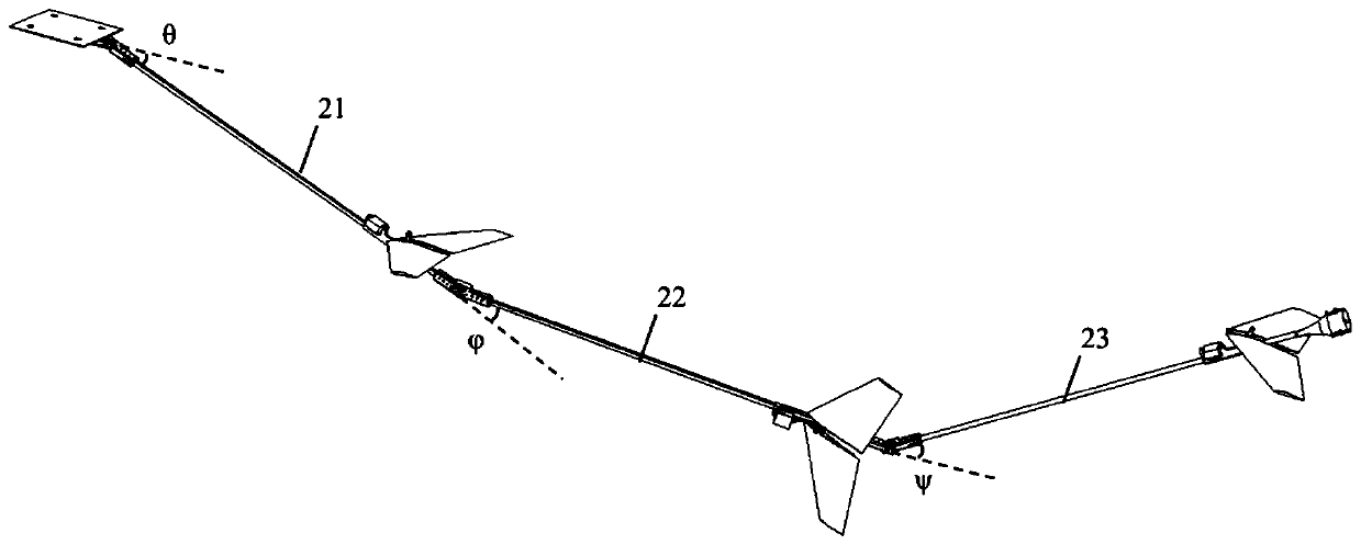
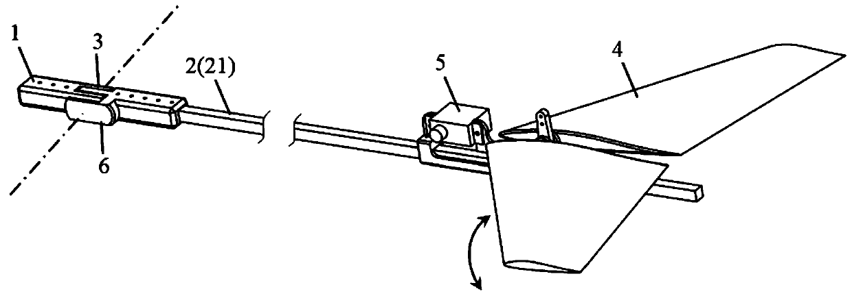
[0046] An embodiment of the present invention provides a mechanical arm based on an aerodynamic rudder surface, such as figure 1As shown, it includes: support 1, rigid pipe 2, ball hinge 3, rudder surface 4, servo motor 5, angle sensor 6, oil delivery pipe 7, docking lock 8, the mechanical arm based on the pneumatic rudder surface in this embodiment is used Air refueling scene.

[0047] In this embodiment, there are three stages of rigid pipes, and the joints between the rigid pipes 2 are provided with supports 1 for connection. The third rigid pipe 23 is connected to the main machine, and the third rigid pipe 23 , the second rigid pipe 22 , and the first rigid pipe 21 are sequentially connected through a single-degree-of-freedom hinge 3 . An angle ...


PUM


Abstract

The invention discloses a mechanical arm based on a pneumatic control surface and a working method of the mechanical arm, relates to the field of butt joint of aerospace crafts, can be suitable for various air butt joint operations, is high in control response speed and accurate in butt joint, improves the safety and reliability of air butt joint, and meanwhile improves the butt joint efficiency.The mechanical arm comprises a rigid pipe system, an angle sensor and an operation end. The rigid pipe system is formed by sequentially and movably connecting a plurality of rigid pipes, the control surfaces are installed at the tail ends of part of the rigid pipes, and the control surfaces are at least two of elevators, rudders and rolling rudders. An angle sensor is arranged at the joint of therigid pipes. One end of the rigid pipe system is movably connected with the operation machine, and the other end is provided with a working end which is an oil conveying port or a butt joint lock catch. According to the invention, maneuvering actions of a butt joint aircraft are effectively reduced, and the butt joint safety and reliability are improved. The mechanical arm is applied to aerial refueling and material supply, a complex mechanical structure is not needed, control force is generated by controlling the control surface, mechanism movement is controlled, and then the effect similar to that of a mechanical arm is achieved.

Description

technical field [0001] The invention relates to the field of docking of aerospace vehicles, in particular to a mechanical arm based on an aerodynamic rudder surface and a working method thereof. Background technique [0002] Aircraft air control mechanisms (such as mechanical arms, hoses, etc.) can be used to perform special tasks in the air between two or more aircraft, such as aerial refueling, material replenishment, etc., which can increase the range and combat radius of the aircraft and increase the number of aircraft in the air. Time, increase airborne equipment or aircraft payload, etc., greatly improve the performance of the aircraft, and have broad application prospects in special-purpose military aircraft. [0003] At present, the air control mechanism of aircraft is mainly divided into hose type (active approach of docking slave aircraft) and mechanical type (mechanical control of parent aircraft). [0004] The hose-type system is widely used in aerial refueling ...

Claims


Application Information

Patent Timeline
IPC IPC(8): B64D39/00G05B11/42
CPCB64D39/00G05B11/42
Inventor 黄紫顾蕴松史楠星吕全辉龚正冯潮周龙赵冬凯
Owner NANJING UNIV OF AERONAUTICS & ASTRONAUTICS
Why Eureka
Try Eureka