Bending equipment and bending method

A bending and equipment technology, applied in electrical components, climate sustainability, circuits, etc., can solve problems such as low yield rate of application and perforation processes

Pending Publication Date: 2020-07-07
上海祖强能源有限公司
View PDF0 Cites 1 Cited by
  • Summary
  • Abstract
  • Description
  • Claims
  • Application Information

AI Technical Summary

Problems solved by technology

[0004] Embodiments of the present invention provide a bending device and a bending method to solve the technical problem of low yield rate in the existing bus bar application and perforation process

Method used


Image

  • Bending equipment and bending method
  • Bending equipment and bending method
  • Bending equipment and bending method

Examples


Embodiment Construction

[0034] The following will clearly and completely describe the technical solutions in the embodiments of the present invention with reference to the accompanying drawings in the embodiments of the present invention. Obviously, the described embodiments are part of the embodiments of the present invention, but not all of them. Based on the embodiments of the present invention, all other embodiments obtained by persons of ordinary skill in the art without creative efforts fall within the protection scope of the present invention.

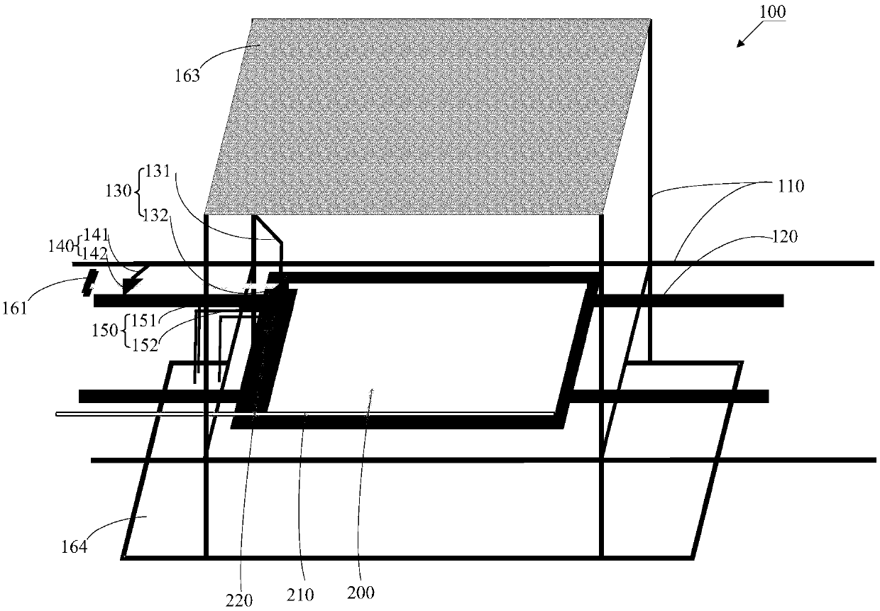
[0035] see figure 1 , figure 1 It is a schematic structural diagram of a bending device provided by an embodiment of the present invention, and the bending device is used for bending and fixing a bus bar to a chip. Such as figure 1 As shown, the bending equipment 100 includes:

[0036] a support 110 and a transmission device 120 for carrying the chip 200, the transmission device 120 is arranged on the support 110;

[0037] The fixing assembly 130 i...


PUM


Abstract

The invention provides bending equipment and a bending method. The bending equipment comprises a support, a transmission device used for bearing a chip, a fixing assembly and a first bending assembly,wherein the transmission device is arranged on the support; the fixing assembly comprises a first moving mechanism and a first pressing sheet, the first moving mechanism is connected with the first pressing sheet, the first moving mechanism drives the first pressing sheet to move, and the first pressing sheet is used for fixing a bus bar on the chip; the first bending assembly comprises a secondmoving mechanism and a second pressing sheet, the second moving mechanism is connected with the second pressing sheet, the second moving mechanism drives the second pressing sheet to move, and the second pressing sheet is used for pushing the bus bar to bend the bus bar. The bus bar on the chip does not need to be manually applied and bent, the technical problem that the yield is low due to low controllability of manual operation is avoided, and the yield and the processing efficiency of the bus bar laid on the chip are greatly improved.

Description

technical field [0001] The invention relates to the field of processing technology, in particular to a bending device and a bending method. Background technique [0002] Existing processes, especially CuInGaSe (CuInGaSe x Ga (1-x) Se 2 , referred to as CIGS) in the mass production process of thin-film solar cells, the bus bar is usually welded to the electrode of the battery chip by ultrasonic technology. The specific process is: two bus bars are respectively welded to the electrodes on opposite sides of the battery chip, and are drilled through the substrate of the battery chip to connect with the junction box at the back, so as to lead out the electricity generated by the battery. The application of the bus bar on the chip and the perforation operations are basically manual operations. Due to the low controllability of manual operation, the yield rate is low. [0003] It can be seen that there is a technical problem of low yield rate in the existing bus bar applicatio...

Claims


Application Information

Patent Timeline
Patent Type & Authority Applications(China)
IPC IPC(8): H01L31/18B21F1/00
CPCB21F1/004H01L31/18H01L31/188Y02P70/50
Inventor 梁变变丁友谊
Owner 上海祖强能源有限公司
Why Eureka
Try Eureka